Hardware Assembly
During this step you will assemble the hardware on the drone.
Bolt on the Motors
Two of the motors are counter-clockwise threaded and the other two are clockwise threaded. Screw the included nuts that came each motor onto the motor shaft so you don’t forget which is which.
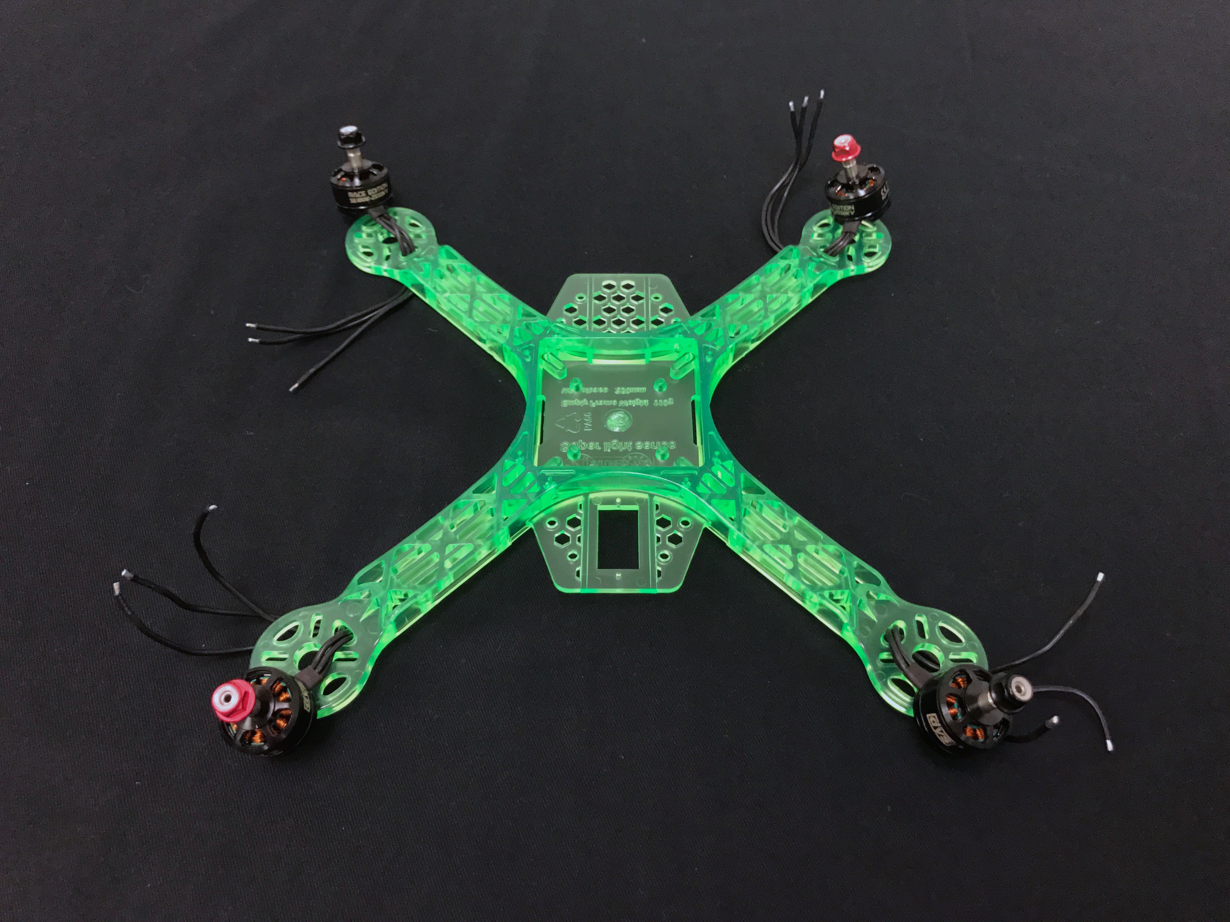
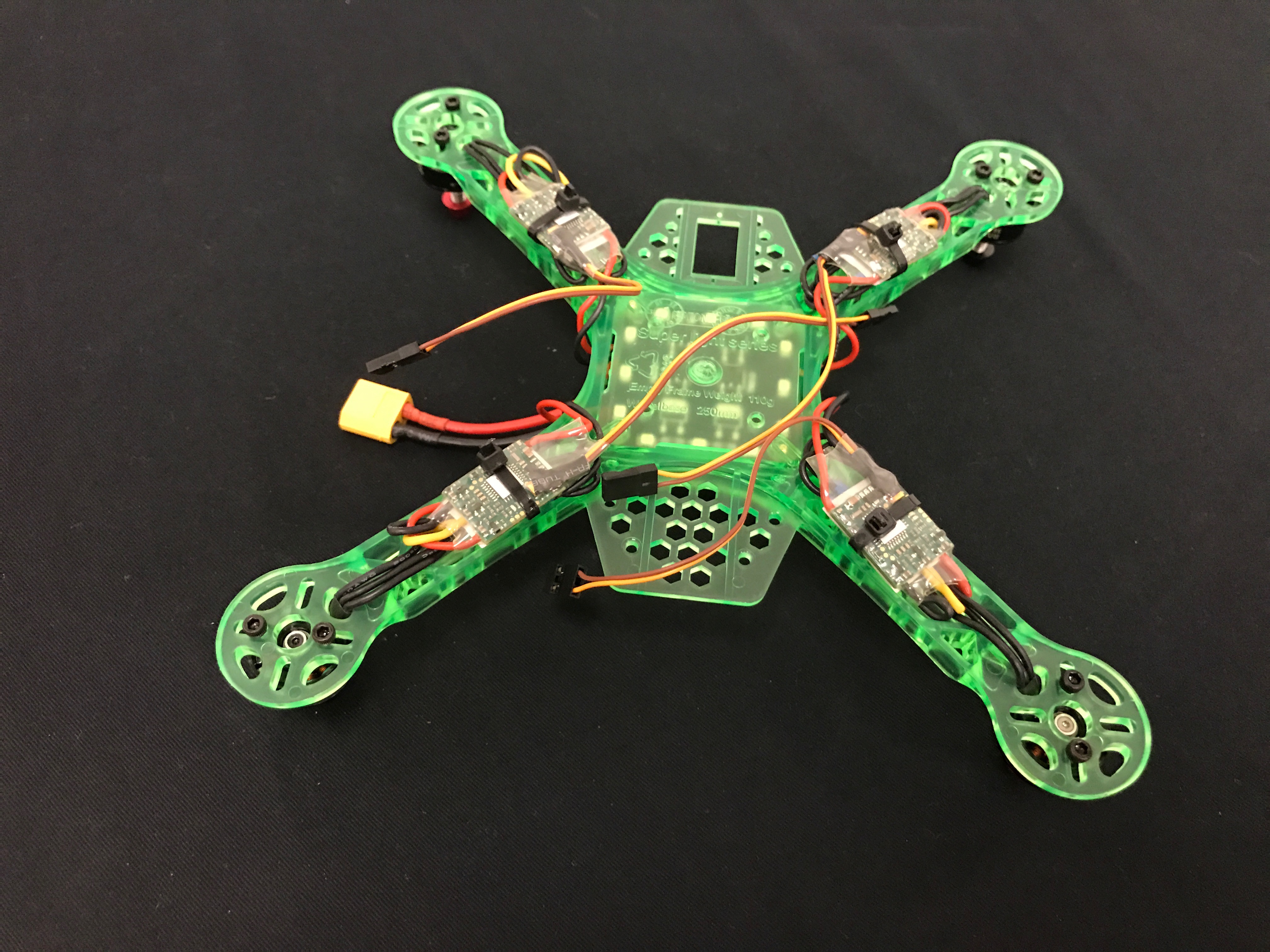
The motors with the red nuts will spin counter-clockwise and the black clockwise, so it is critical that they are attached to the correct arms. The front right motor will spin CCW, and the front left motor will spin CW. Diagonal motors spin in the same direction.

The side of the frame with the small hexagonal hole pattern is the front.

In order to ensure the nuts tend to tighten during flight instead of loosen, you want each nut to thread in the opposite direction as its motor spins. For example, this means the front right motor’s nut should tighten in the CW direction. The image below shows the correct motors in the correct places, with red in the front right and back left, and black in the front left and back right. When mounting the motors, make sure to route the wire through the hole in the frame to the underside of the frame before bolting on the motor.
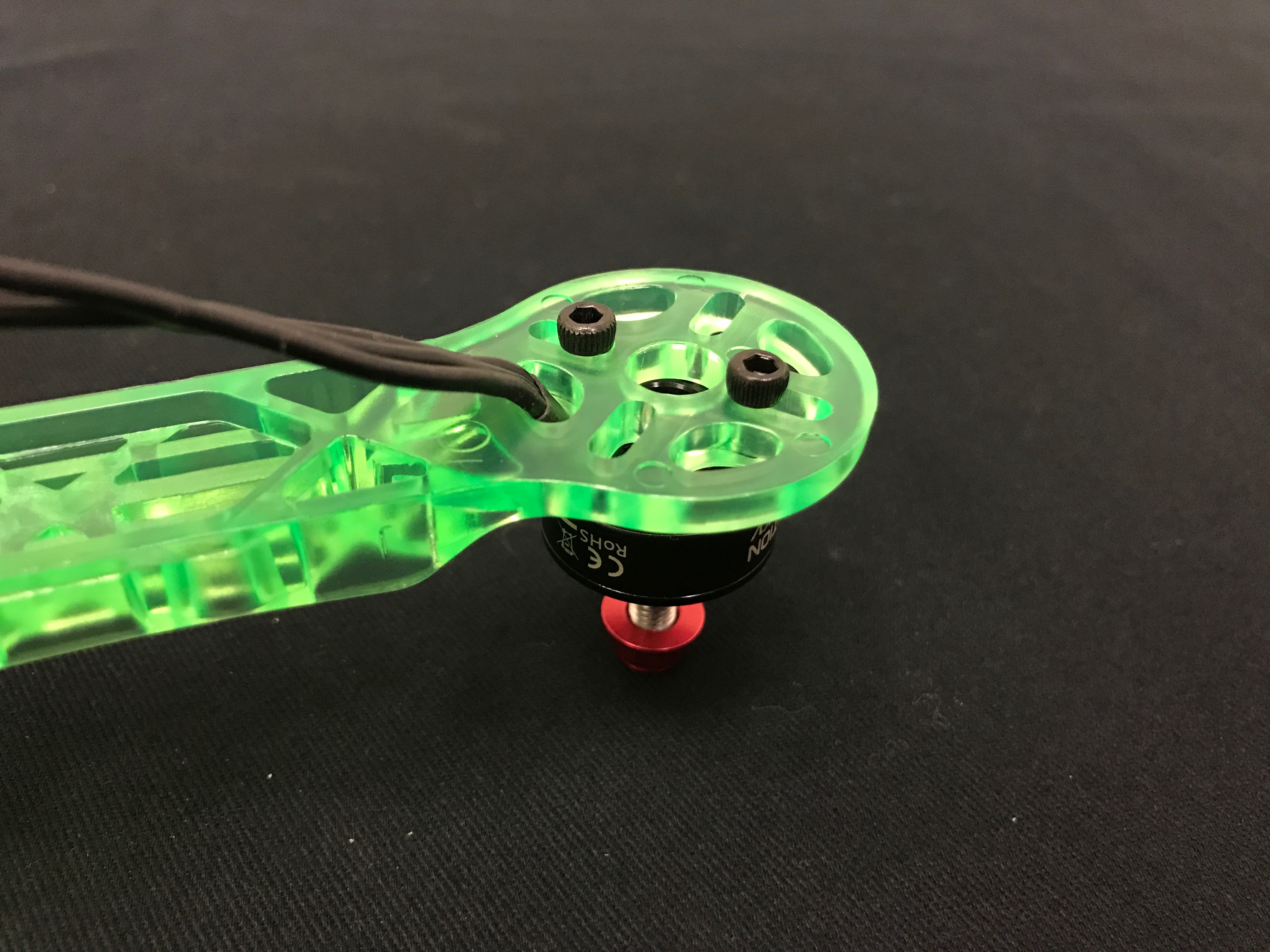
Use two of the long M3 bolts included with the motor and screw them in tightly.
Solder the PDB
Just like the human body has a circulatory system to carry oxygen-rich blood to wherever it is needed, the drone has a power distribution board (PDB) to take the all-important battery power and send it to every component. In this step, you will solder 4 ESCs (electronic speed controllers), a BEC (battery eliminator circuit), a battery lead with XT60 connector, and a battery monitor lead to your PDB (power distribution board).
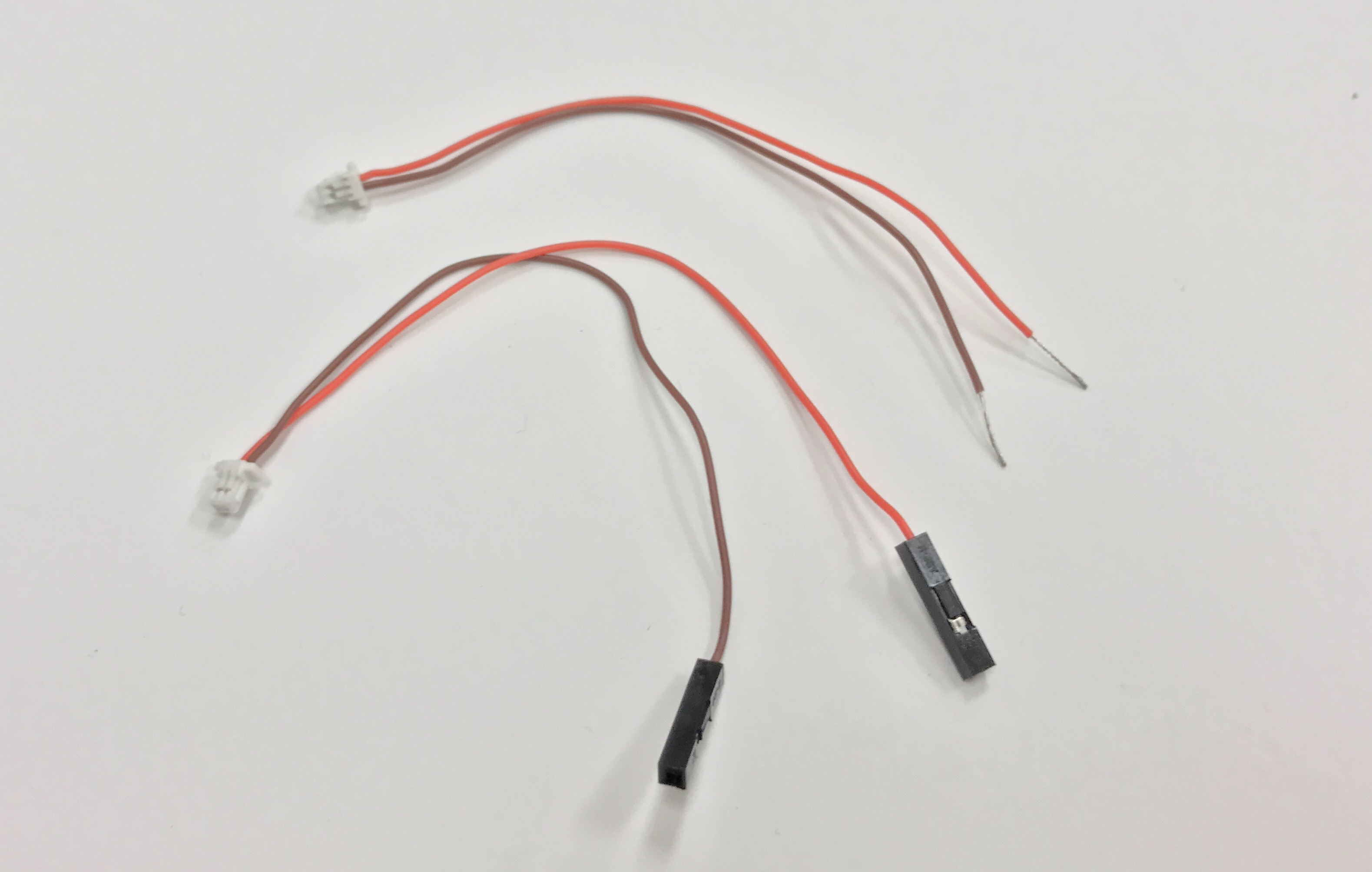
Strip Wires
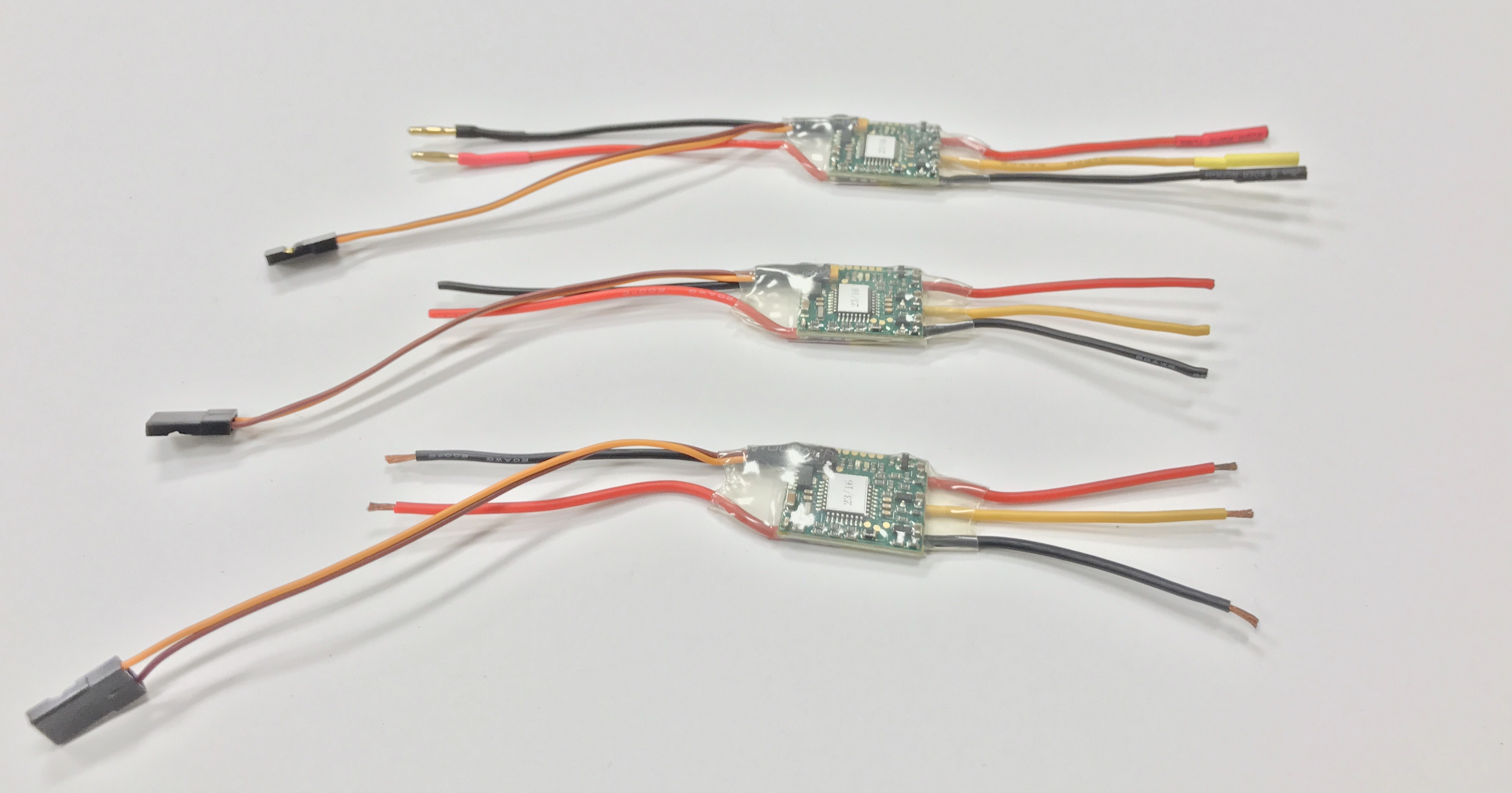
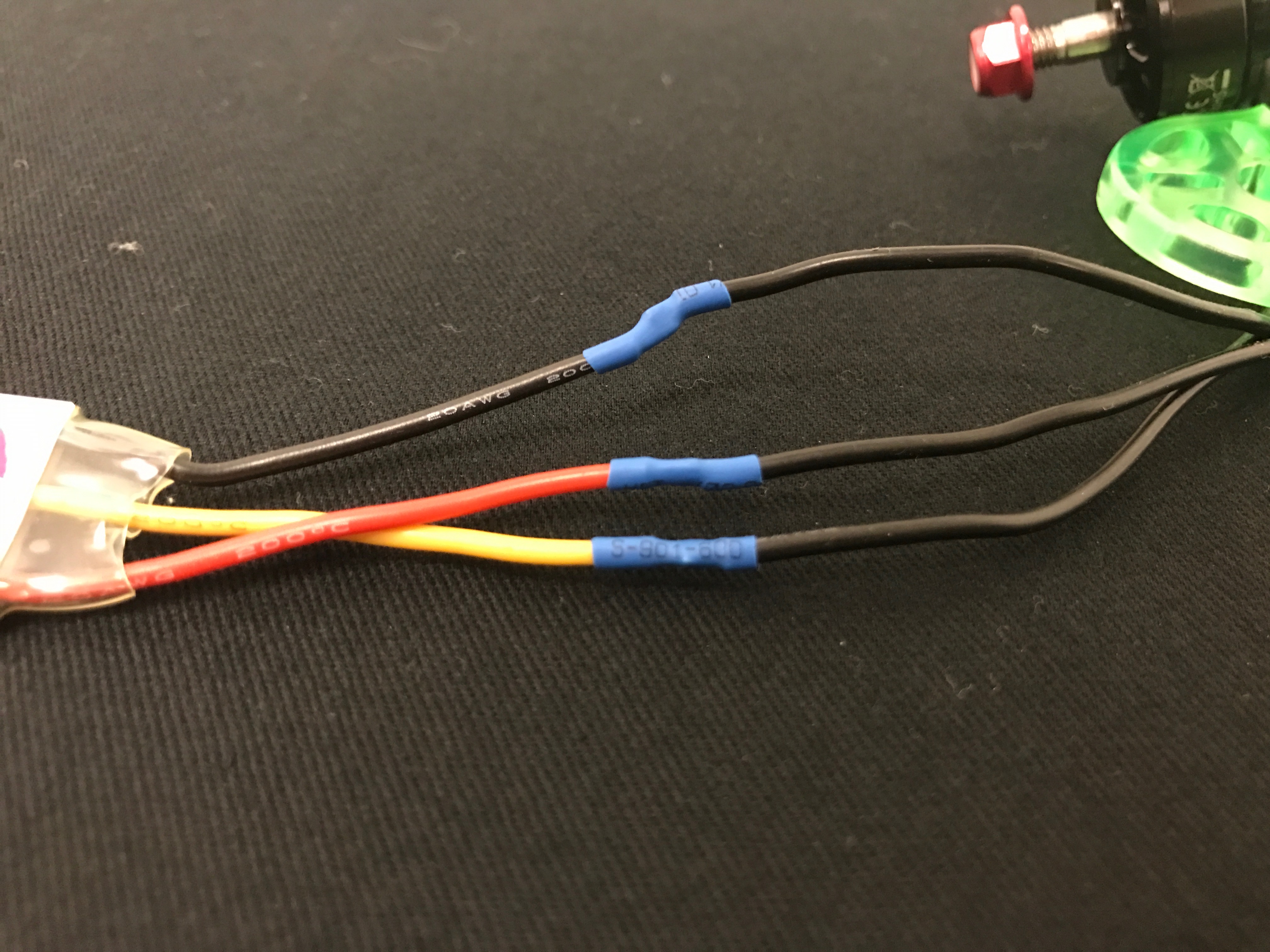
Cut off all the bullet connectors on the thick wires of the ESC as close to the connector as possible. Leave the PWM signal connector alone. Strip 0.5 cm from each of the wires you just cut. You need to do this for the two input wires and the three output wires, as shown in the picture:
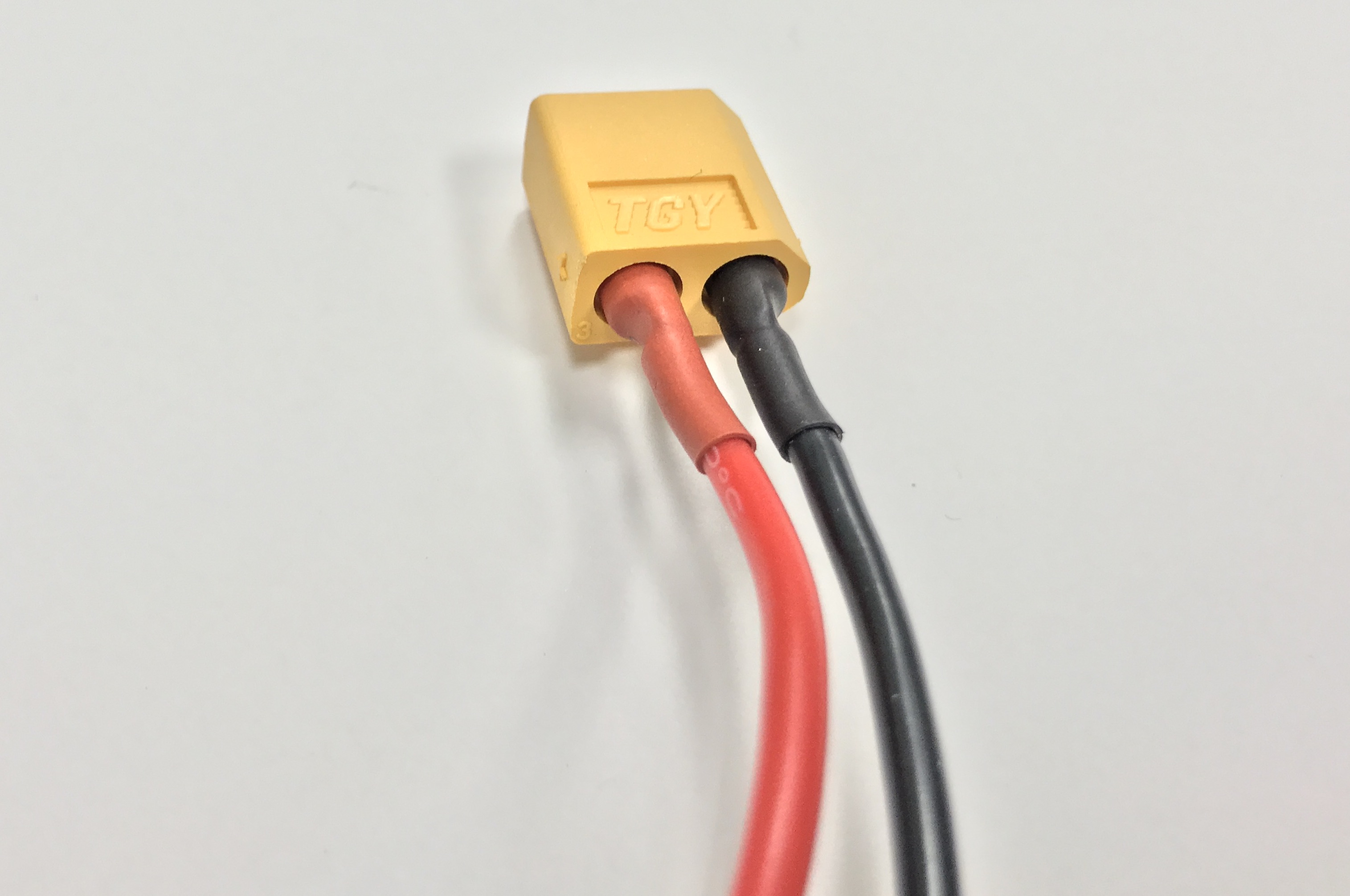
Strip 0.5cm off your battery lead with XT60 connector.
Inside the plastic box labeled, SKYLINE 32, find the battery monitor lead, cut off the two larger connectors, and strip 1cm.
Tin PDB and Stripped wires.
Tin all 20 ESC leads. Twist the battery monitor leads around the BEC leads and tin.
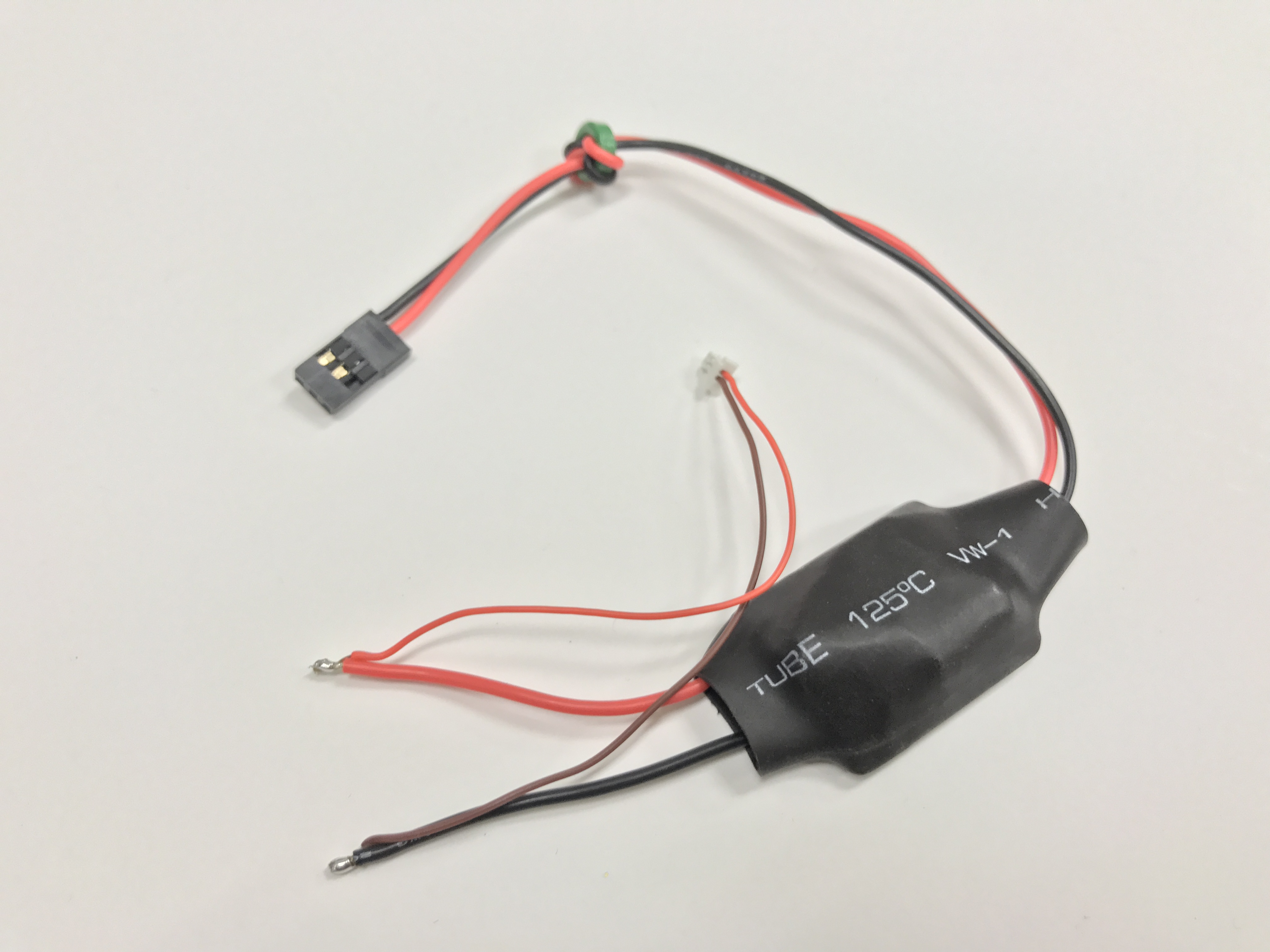
Thoroughly tin the battery lead with XT60 connector. It is important that solder flows all the way through the exposed wire.

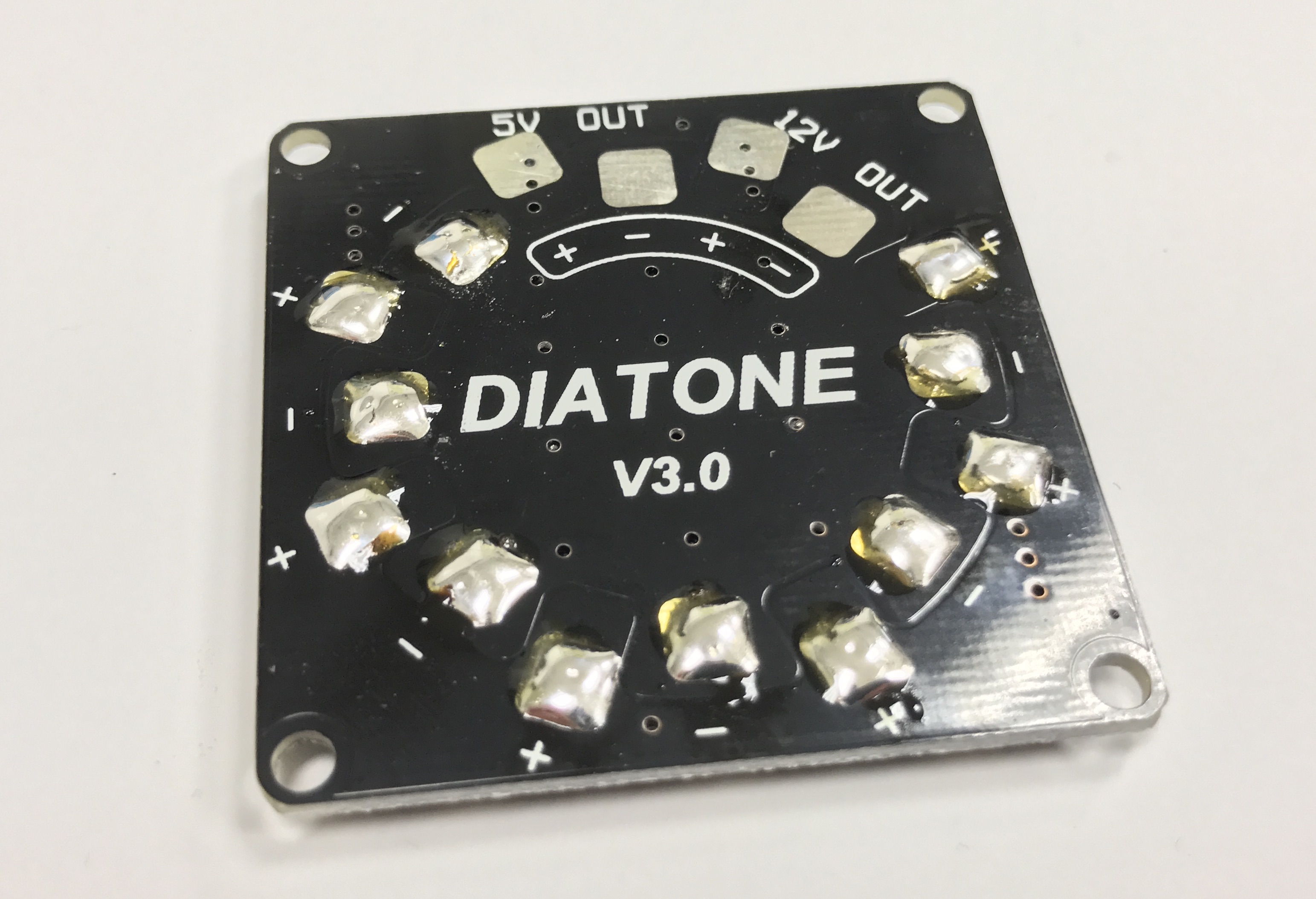
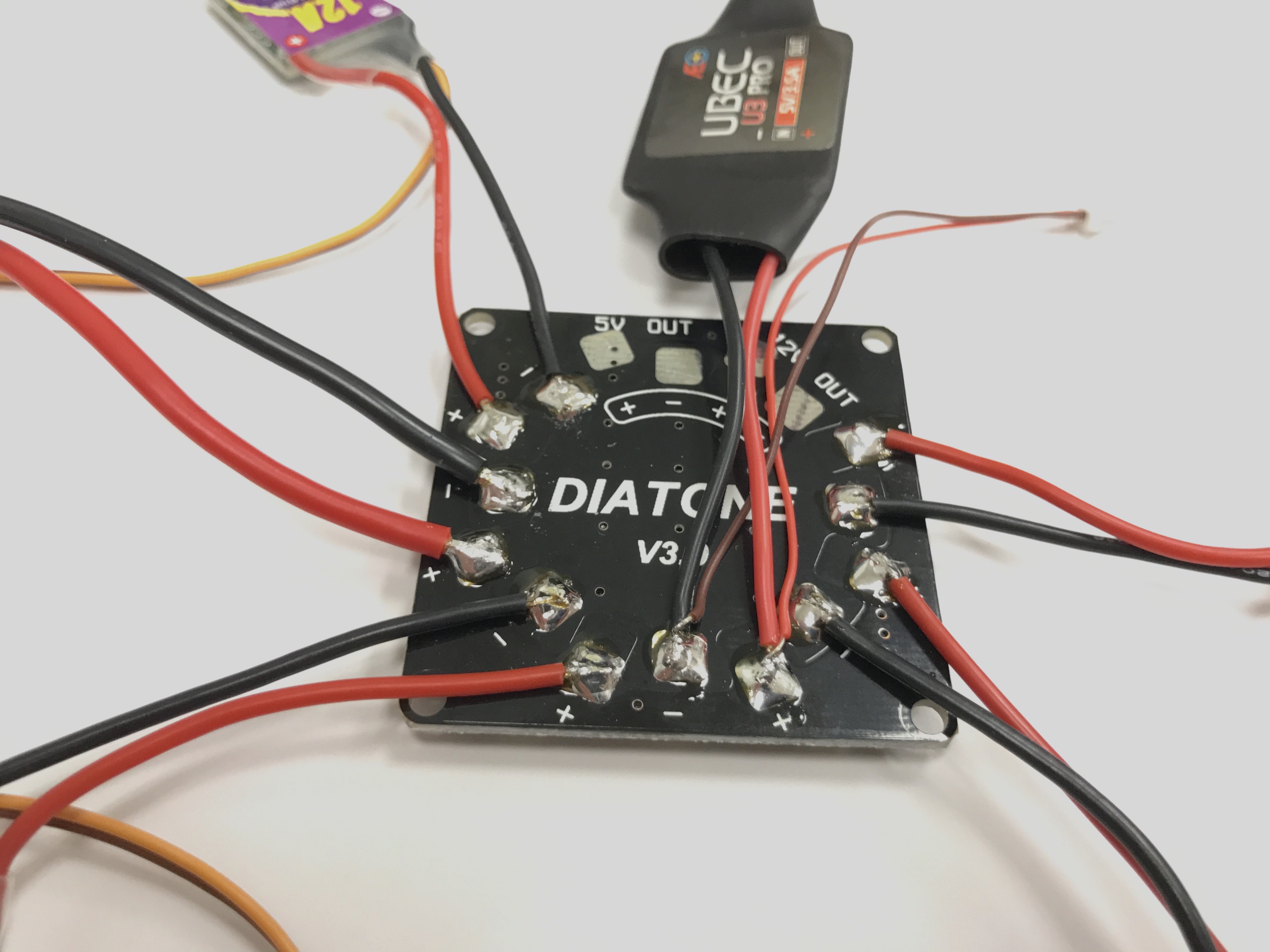
Tin the pads on the PDB as shown. Leave the 5V OUT and 12V OUT pads alone.
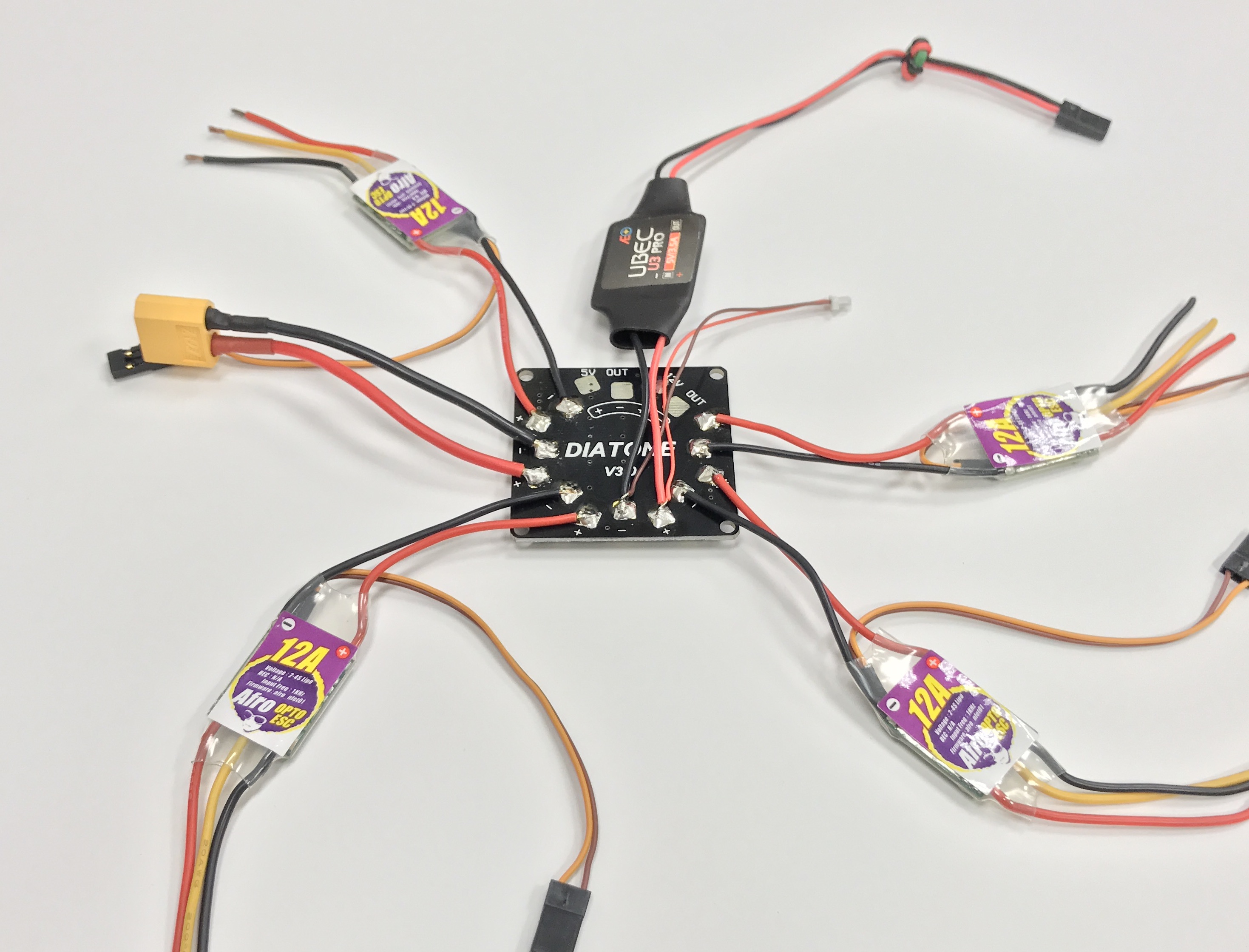
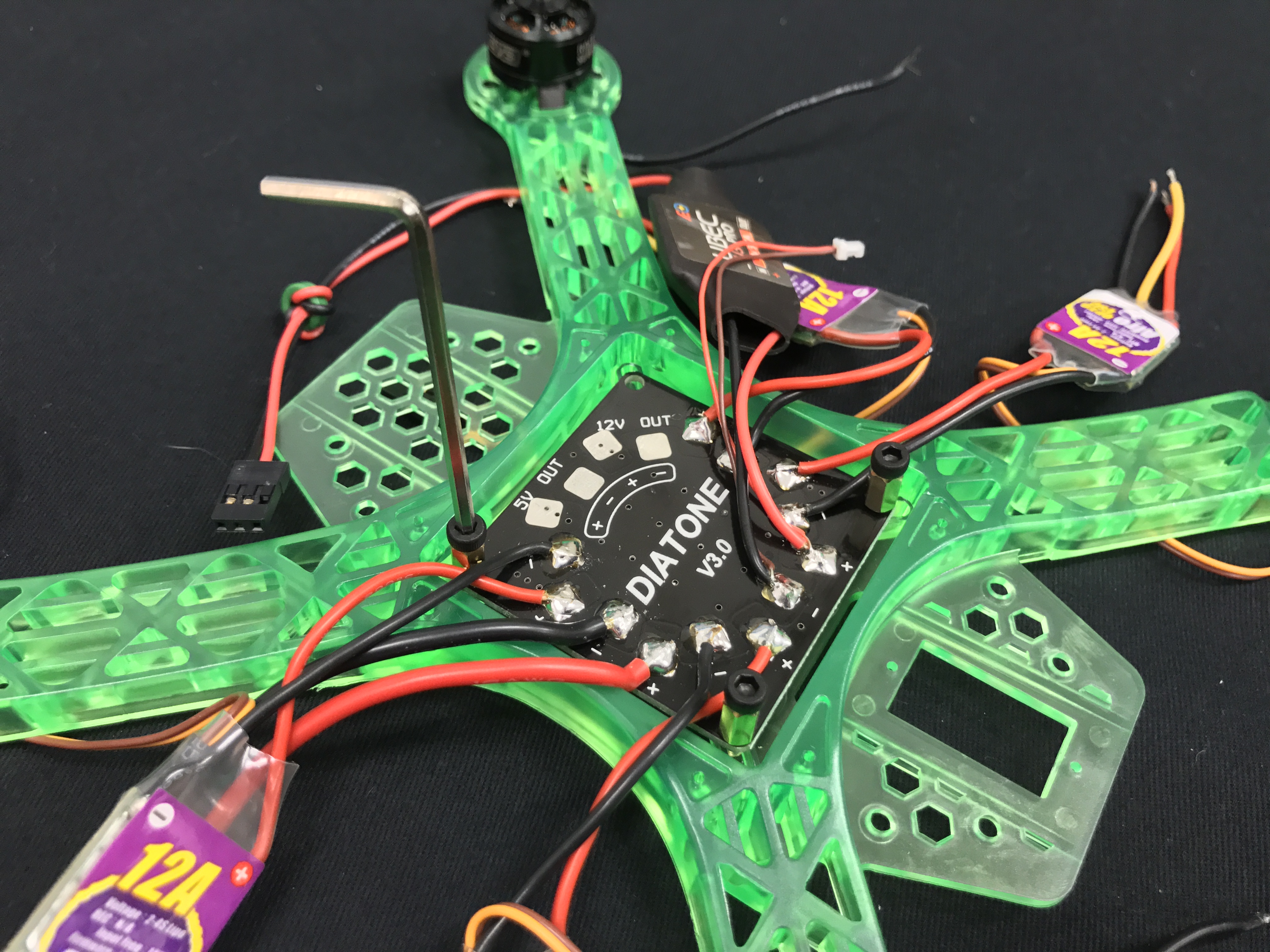
Connect components to the PDB
Solder the tinned components to the PDB as shown. Make sure Red goes to + and black/brown goes to -.
Screw the short M3 bolts into the brass 6mm M3 standoffs.
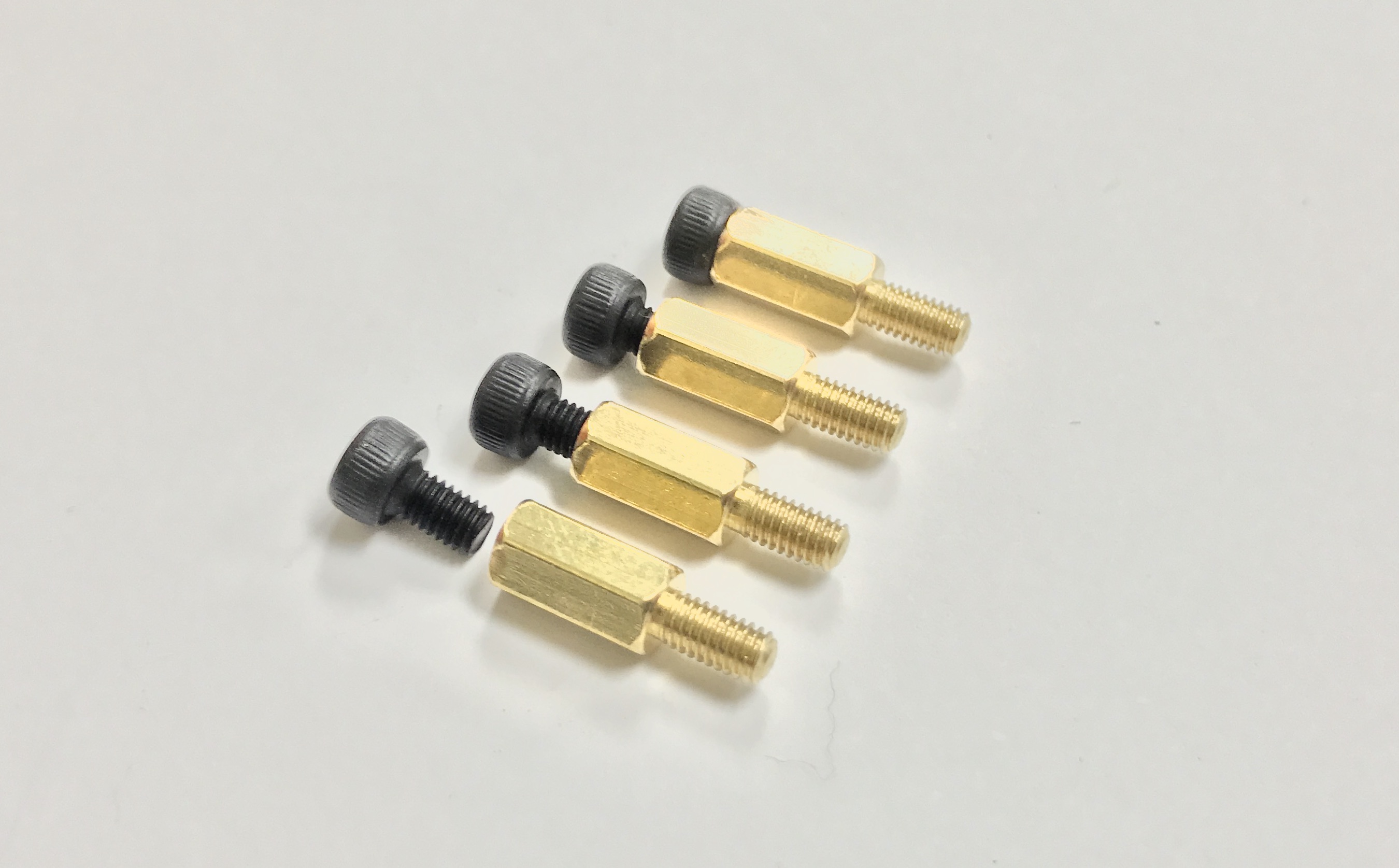
Use a hex key to screw the standoffs through the PDB into grooves in the frame in the shown orientation. Apply a downward pressure as you are turning to ensure the standoffs bite into the plastic. Be careful not to overtighten the standoffs and strip out the groove.
Solder ESCs to Motors
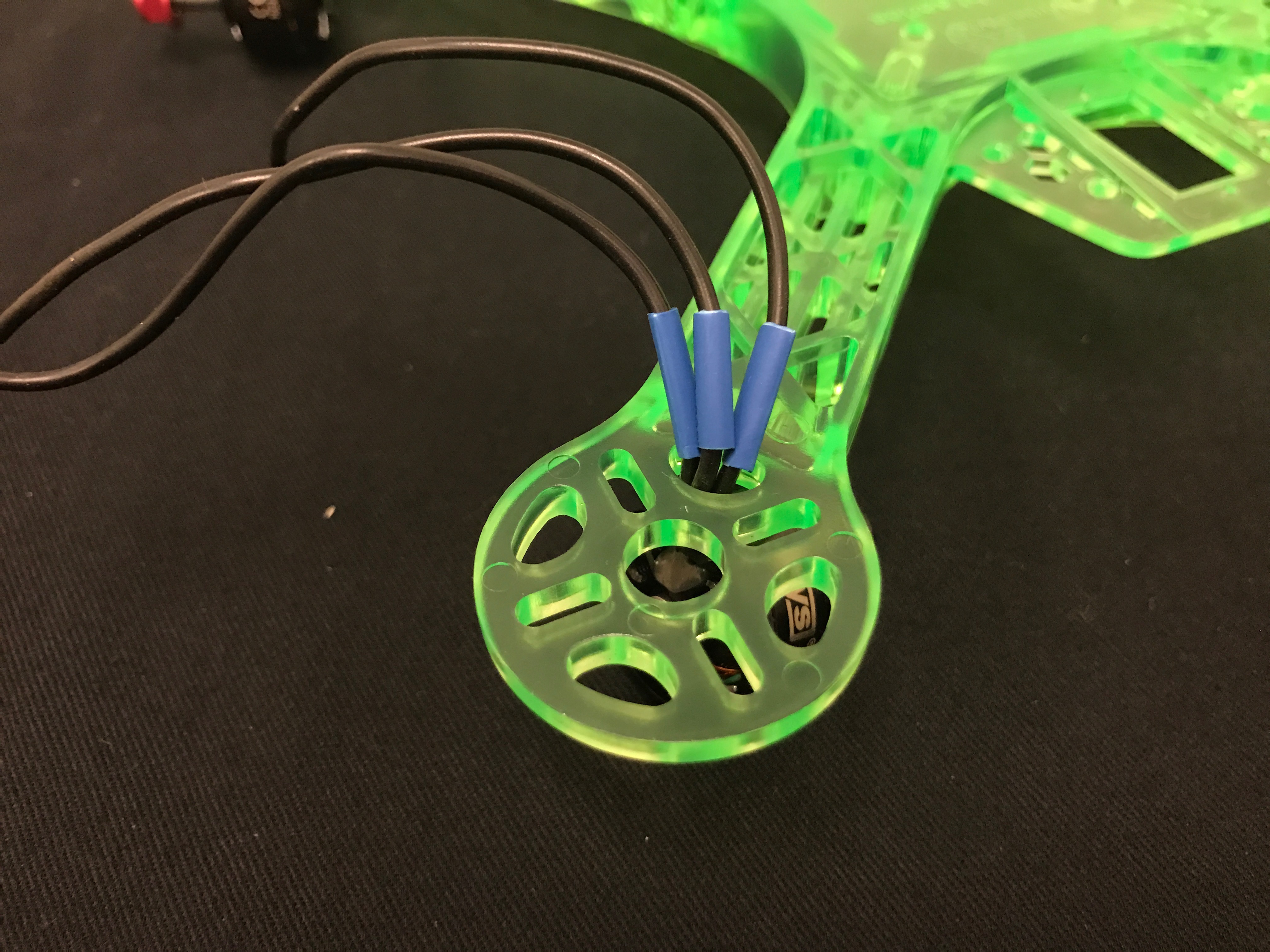
Place your 3mm diameter heatshrink tubing cut to 1cm sections onto each of the motor leads.
Tin the ESC wires thoroughly if you haven’t already. Tin the motor wires as well. (Note: They come pre-tinned, but with a different, higher temperature solder and not quite enough of it)

Solder the ESC wires to the motor wires. It does not matter which ESC wire is connected to which motor wire. However, routing will be easier if you make sure they are not too twisted.

After soldering each motor to its corresponding ESC, move the heatshrink over the solder joint and use a heat gun to shrink it.
Routing
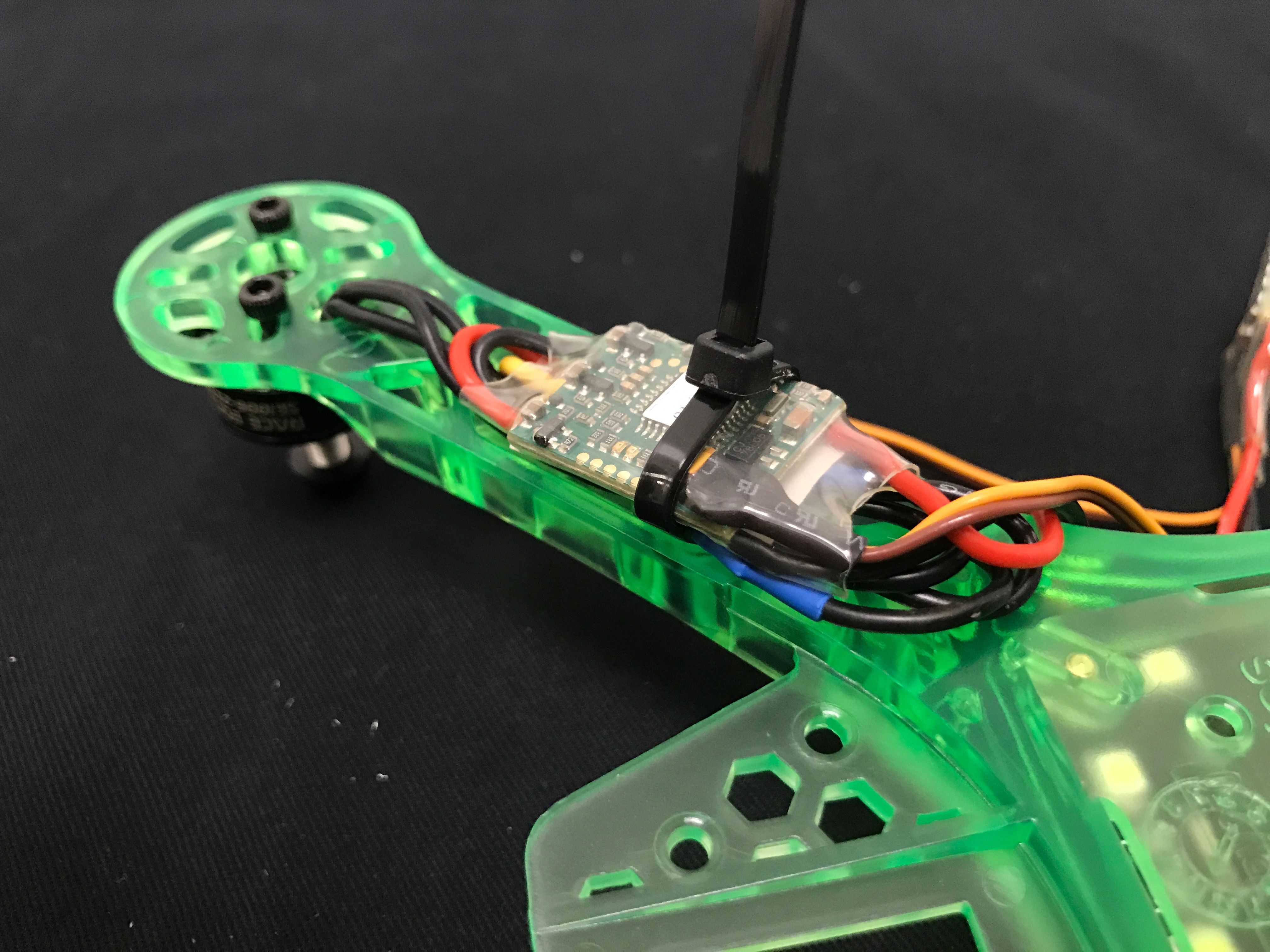
Now everything has been soldered, and you can start worrying about wire management. Route ESC wires nicely with zip ties. You need to ensure that the wires will not be cut by the spinning props. It is best to secure the ESCs and wires underneath the frame.
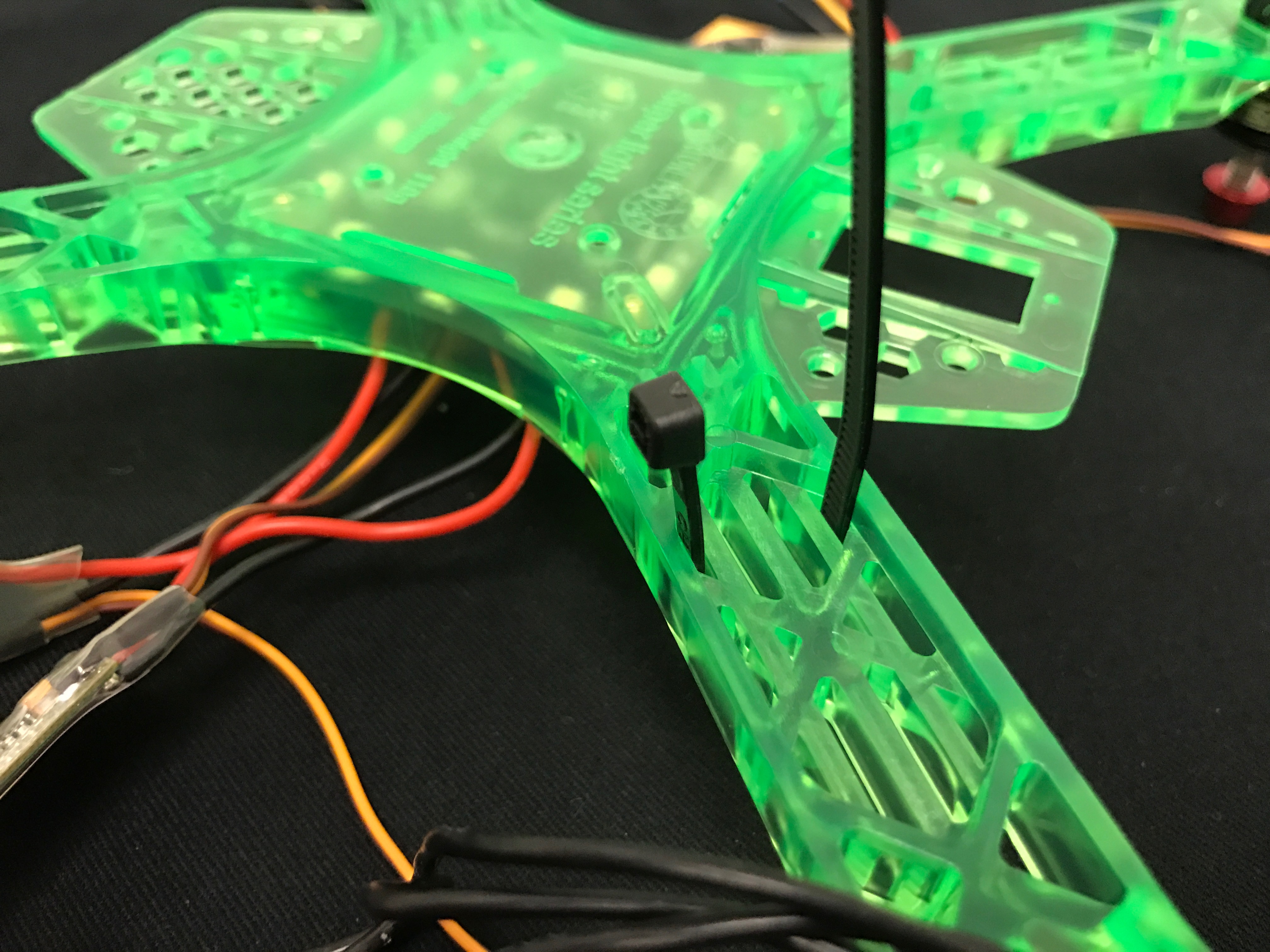
Route the ziptie through the holes in each arm as shown. It is important to go through the holes and not around the arm so the zipties doesn’t slide around.
Fold the motor wires up neatly underneath the ESC and place it down into the ziptie.
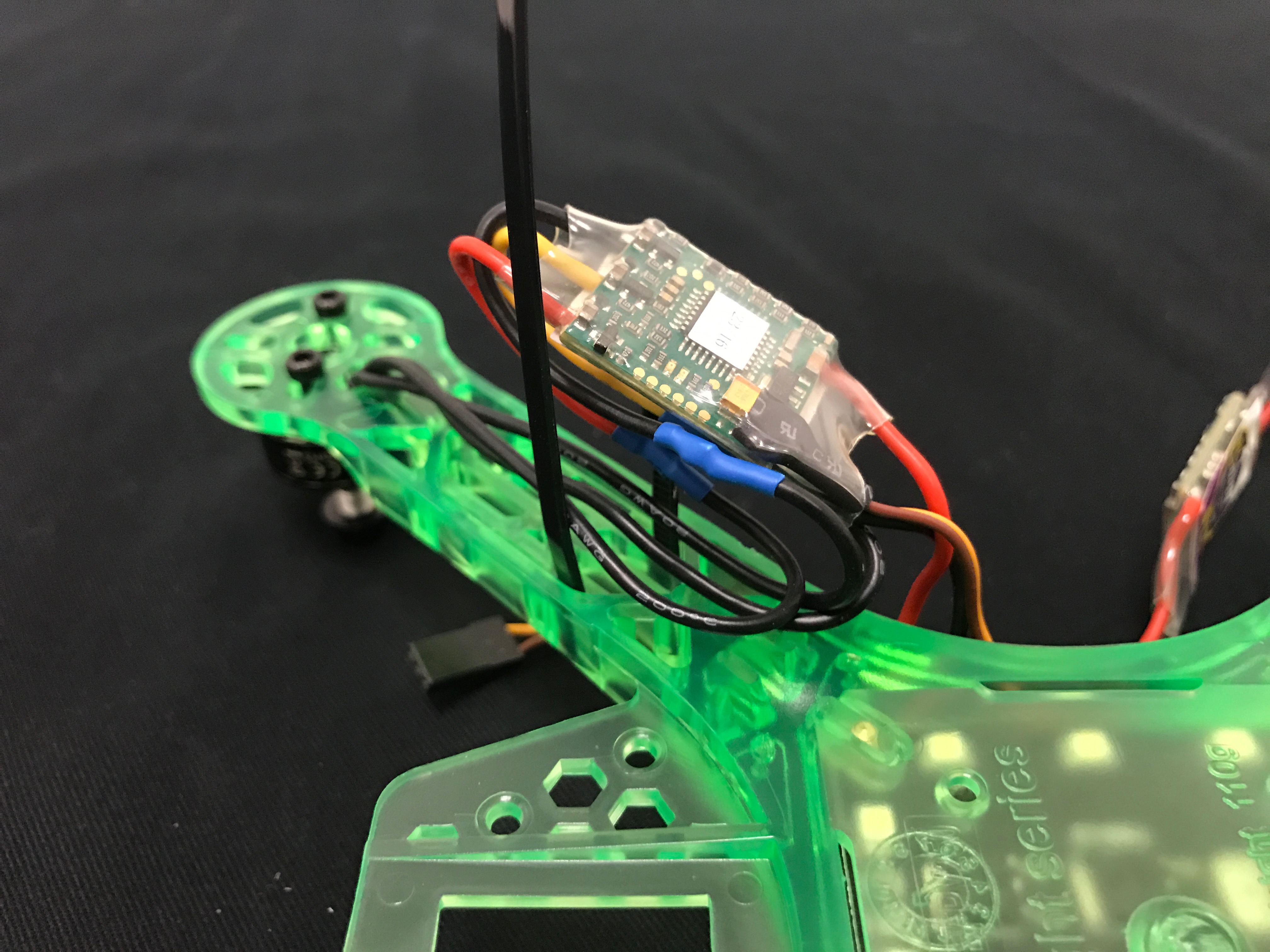
Cinch the ziptie down over the ESC (pretty tight) doing your best to make sure the ESC lies flat.
And Fin!
Camera Attachment
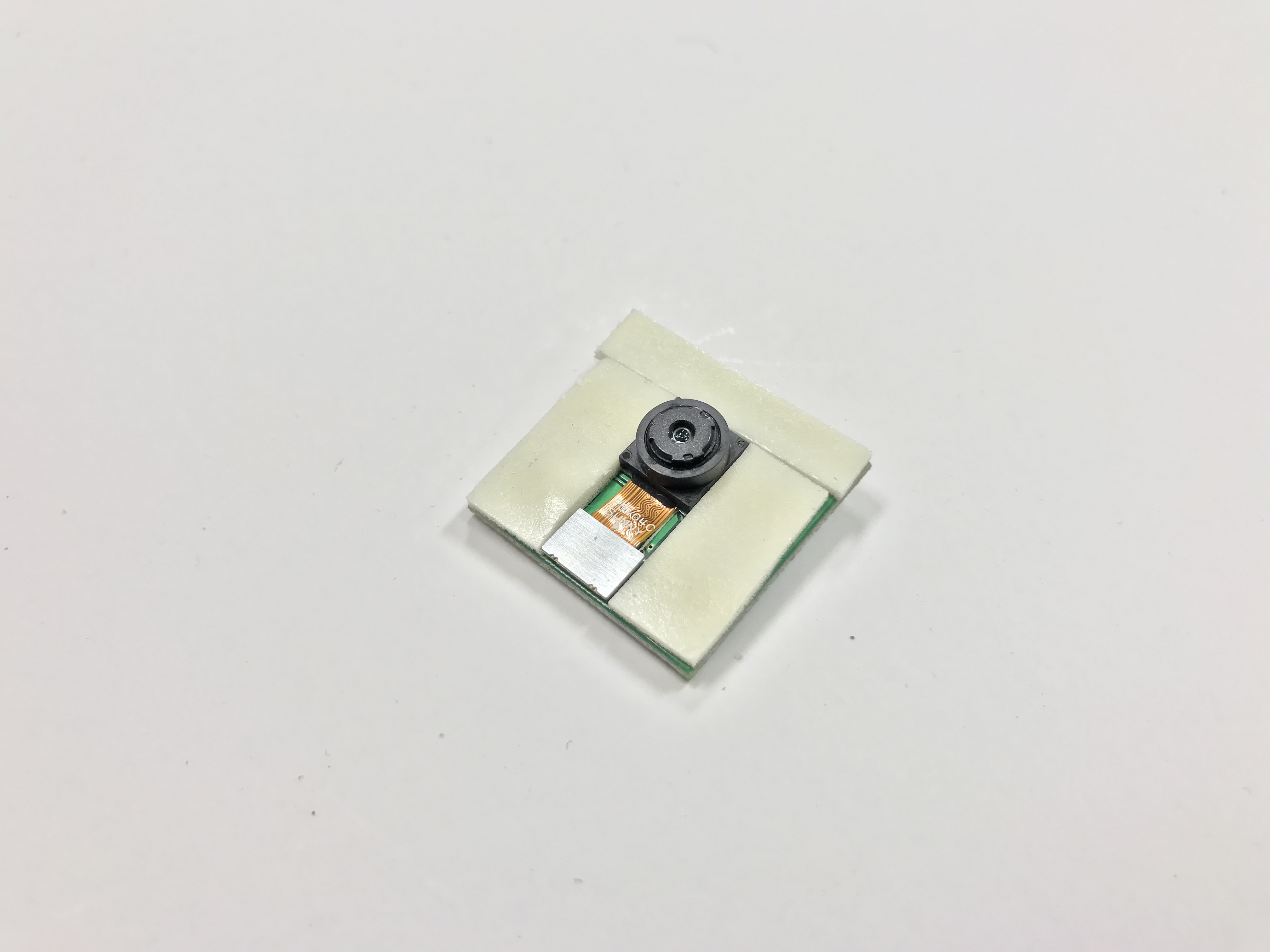
Now you will attach the camera to your frame. Place double-sided sticky tape around the camera, as shown in the picture.
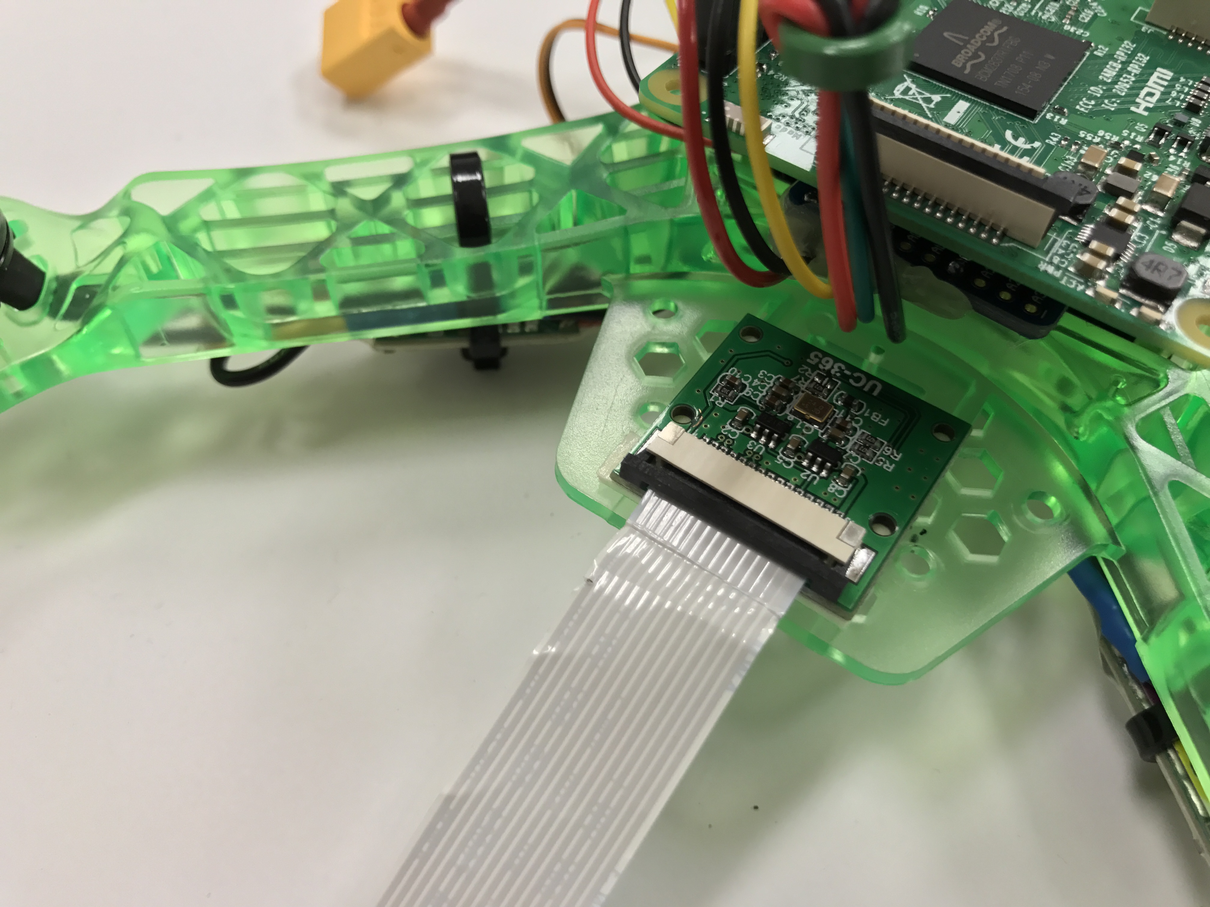
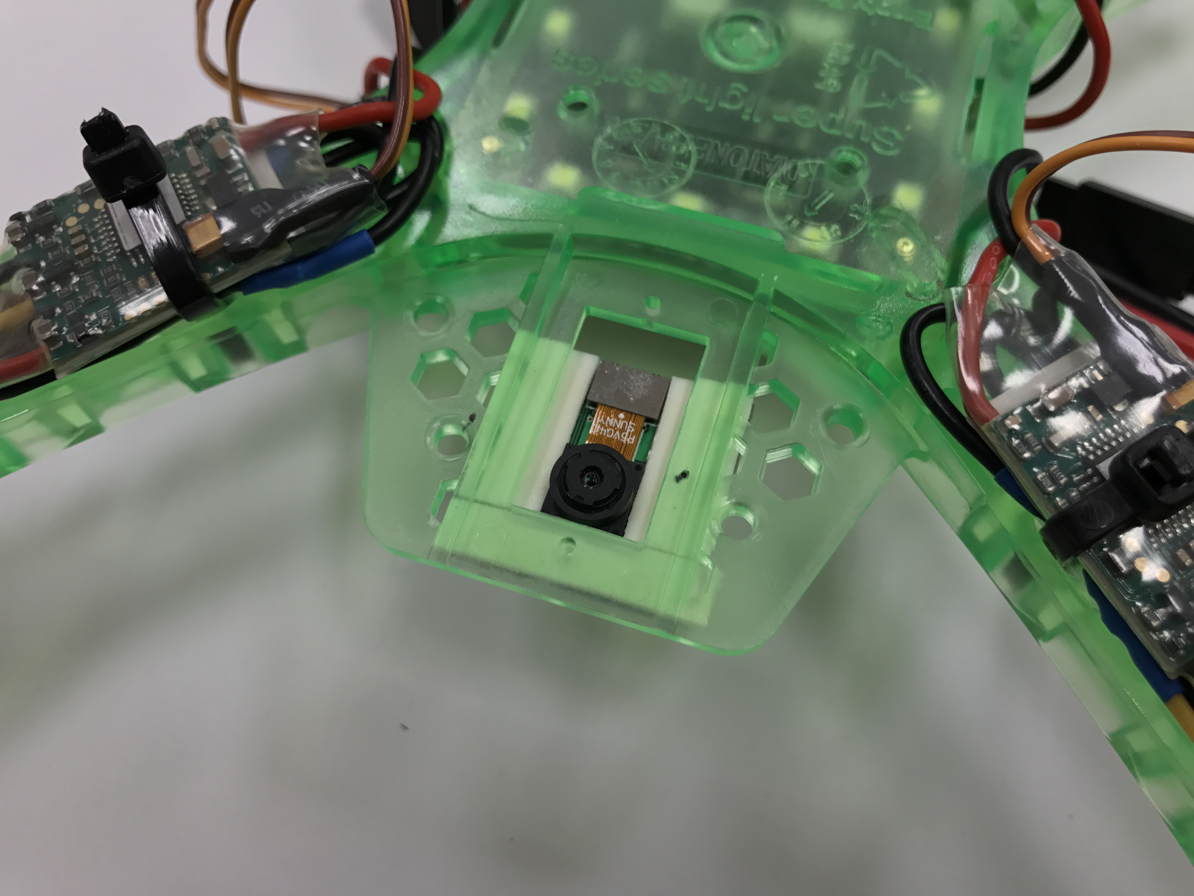
Place the camera through the hole in the back of the frame, as in the picture. Be sure that the connector is facing out from the frame so you will be able to plug in the camera cable (you don’t need to plug it in now though). Make sure it is aligned with the frame! Any missalignment in the camera will mess with your computer vision!
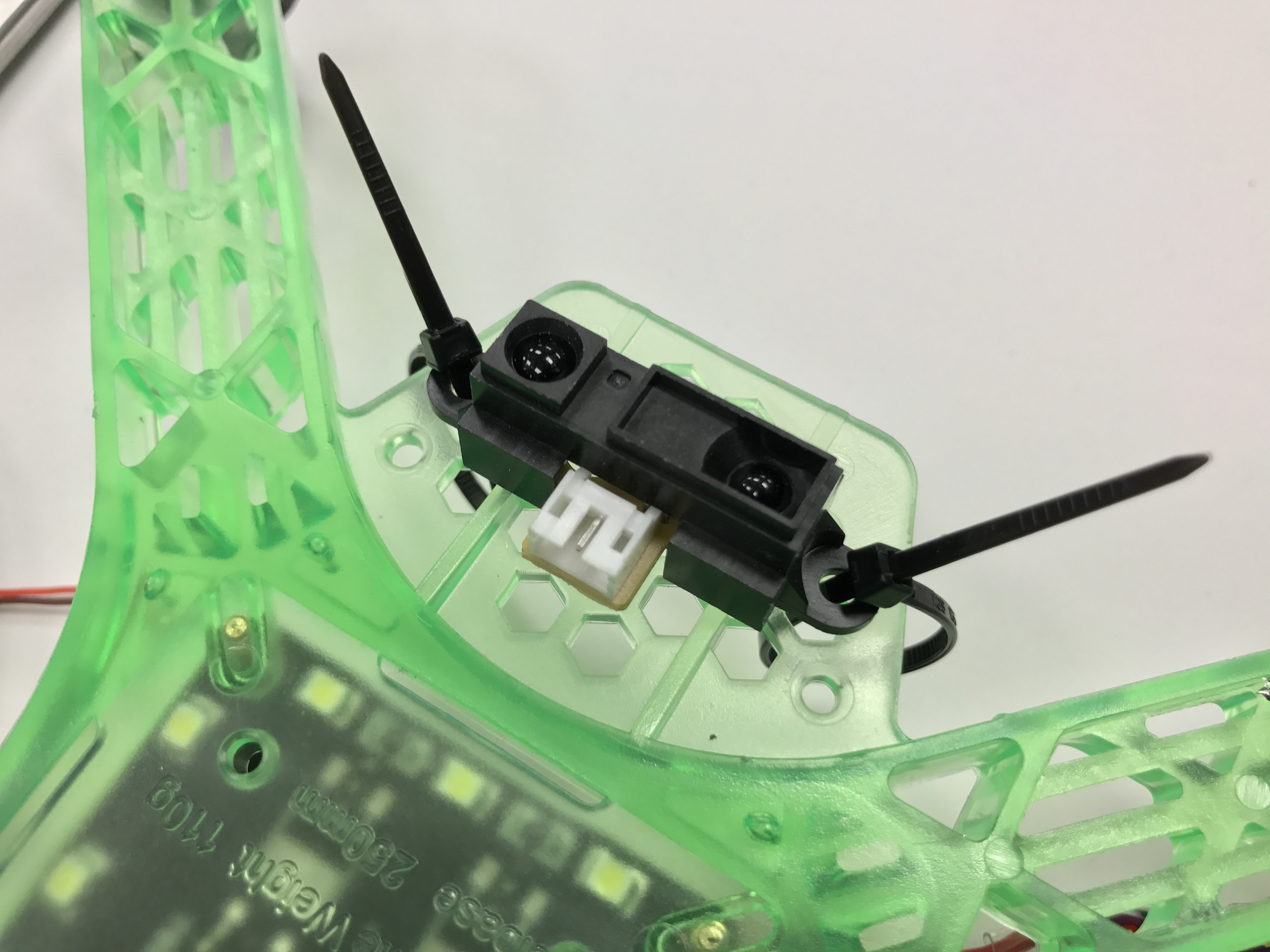
IR Attachment
Zip tie the IR sensor onto the bottom of the frame’s front platform, as in the picture.
Checkoff
Come to TA hours and have a TA verify that all your hardware is set up correctly before continuing.