There are a number of reasons why my cart-and-pole project was not terribly successful (ok, so it was a failure). I was aware of the potential problems before I started on the project but I was bull headed enough to ignore the problems. (Perhaps I can get away with pretending like I had a sound pedagogical reason for proceeding as I did.) Knowing that it will in many cases fall on deaf ears, allow me to give you some advice, advice that I should have followed if I was really interested in building a robot that balanced a pole: think first and then implement.
Implementing a robot includes designing, building and debugging both hardware and software. The thinking part should include devising and running experiments to better understand sensors and motors and building and experimenting with simple prototypes of components such as a drive train or a subroutine for interpreting the output of a sensor. Extensive experiments with sensors and components is a critical part of design in large part because your robot will be interacting with the real world and experience shows that just thinking about things is likely to lead you astray - the real world is full of surprises.
Fred Martin has some very useful advice for fledgling robot builders. Martin designed the Handy Board which was used in earlier versions of CS148; he is the author of several papers on Legos and robots in education and most recently "The Art of Robotics: An Introduction to Engineering", a university-level textbook for creating a hands-on introductory engineering course based on robot design which grew out of his work on the MIT LEGO Robot Design Project (6.270). The original course notes for 6.270 are available online at MIT; I especially recommend Chapter 4 of The 6.270 Robot Builder's Guide for useful tips on building things out of Legos. Martin also has some interesting things to say about the art of building robots in his thesis. I highly recommend Chapter 4 and Section 4.1 in particular: 4.1.1. The Omniscient Robot Fallacy.
So what could I have known or found out about the cart-and-pole problem before I started playing with Lego bricks and RCX code? Let's assume for a moment that you've never heard of the academic and engineering disciplines known variously as automatic control systems, dynamical systems, and cybernetics and so you aren't aware of the theoretical limitations. In this state of blissful ignorance, the first thing you might do is to try to balance a pole on the palm of your hand. If you try this, you'll notice a couple of things: long poles are somewhat easier than short poles, you have to move pretty fast, abruptly changing direction in order to keep the pole upright, and if the pole ever gets more than 10 or 15 degrees out of vertical you have to make some pretty drastic steps to try to restore balance and even these dramatic moves can often fail.
How do these observations translate into specifications for robot hardware? You're going to need relatively powerful motors that can exert high torque, accelerate and reverse direction quickly, and perform well across a wide range of velocities. You're going to need sensors and code to accurately determine the angle of the pole with respect to vertical and the change in (derivative of) the angle. You might also need to know the velocity and acceleration of the cart (the first and second derivatives of the position of the cart) as you'll notice in trying to balance a pole that your response has to take into account how fast your hand is moving at the time you take a corrective action.
The experiment trying to balance a pole on your hand should provide you with some first-hand experience of what the critical factors are in the case of the cart-and-pole problem. You could also learn a lot by consulting a textbook or talking to a professor or graduate student in engineering or applied math. The cart-and-pole problem (often referred to as the inverted pendulum problem in textbooks) is a well studied problem in automated control. It is interesting from both practical and theoretical standpoints.
An expert in mathematical control theory could model the lego version of the cart-and-pole problems (you'd have to provide her with torque profiles, masses, and measurements of the pole and other physical parameters) and tell you whether or not you'd be able to balance the pole - at least to a first approximation. She'd also be able to provide you with advice about what the form of controller you should use.
There is a simple but powerful class of control systems called PID (for Proportional Integral Derivative) controllers. The basic idea is that the output of a PID controller should be a linear combination of the error, the integral of the error, and the derivative of the error. In the following equations, the error at time t is notated e(t) and is the difference between the actual (observed) value v(t) and the desired (set point or target) value s(t) of the parameter that we want to control:
![]()
The general form of a PID controller with output parameter u(t) is shown below. In this equation, each of three components - proportional, integral and derivative - has its own coefficient (constant) which determines the contribution of that component to the linear combination.
![]()
While the above equation typically appears in mathematical treatments the following formulation is often used in practice.
![]()
There are plenty of applications for which you can design a controller in which the output is simply proportional to the observed error, i.e., a PID controller in which the coefficients for the integral and derivative components are zero. Indeed lots of problems that will come up in working with Lego robots can be solved by simple proportional control. However, there are problems that cannot be solved with proportional control alone - at least not as long as you're limited by physics. Note that if your sensors were perfect and you could respond instantaneously, then you could control anything. It is the uncertainty resulting from noisy sensors and the fact that information about the state of the environment is frequently delayed in processing that give rise to the need for a systematic treatment of control.
Mathematical control theorists have a very precise notion of what it means for a system to be controllable. Roughly speaking, a (dynamical) system is controllable if for any given (target) state of the system, e.g., the pole in the upright position in the case of the cart-and-pole problem, it is possible to achieve that state (drive the system into the target state by controlling one or more of its parameters) in a finite amount of time. This is not a terribly demanding criterion and it does not imply, for example, that such a system is easy to control.
Stability is another property of dynamical systems which implies that small changes in input or initial conditions do not result in large changes in system behavior. Stability is not a prerequisite for being able to control a system, but it makes the task of designing a control system somewhat easier. The system describing the cart and pole problem is not stable, but it is controllable. Control systems engineers often take a system which is not stable and make it so by adding components, e.g., springs, dashpots, frictional surfaces, that serve to damp oscillations and thereby attenuate the systems response making it easier to control. If you're interested in an introduction to mathematical control theory, see Chapter 2 and Chapter 4 of [Dean and Wellman, 1991] for a discussion of dynamical systems, controllability and stability, and PID controllers; in particular, Chapter 4 shows that a controller with only a proportional component cannot control the cart-and-pole problem but that a proportional plus derivative controller can. It's pretty clear in the case of the cart-and-pole problem why accounting for the rate of change of the angle (the derivative component) is important in balancing the unstable pole.
We're not going to emphasize the mathematics of control theory in this class, but it's good to know a little about PID control. I started working on some introductory lecture slides on PID control but then I found an article by Vance J. VanDoren in the March 1998 issue of Control Engineering that I thought provided a good practical introduction to the basics. The article describes a simple cruise controller for an automobile. Read the article carefully and then we'll draw on the basics to build a somewhat more complicated controller.
In many applications, several PID controllers might be combined to control a complicated process. Typically there are multiple error signals that we want to keep track of and multiple variables that we want to control. In the following, we'll describe an extension of the motor controller in VanDoren's article. As a practical application, we'll build a controller for a version of Dave Baum's Tankbot. The controller for the Tankbot will include three separate controllers, one for each of the two tracks and one to coordinate the two tracks.
Motors seem to get short shrift in the popular books on building robots with Lego Mindstorms. Dave Baum doesn't talk a lot about motors in his book [Baum 1999] and Knudsen [1999] has only a little more to say about the different motors designed to work with Legos. You're lucky that the geared motors (part number 5225) that come with the RIS are very well behaved little motors and relatively easy to control. However, they still require some coaxing to make them do your bidding.
The motor controller that Baum [1999] describes in the Tankbot chapter of his book (Chapter 5) is an open-loop controller; the controller simply sets the (voltage) levels for the motors and the wheels turn as long as they aren't wedged or overloaded. The problem is that they will turn at different speeds depending on the load, the incline, and any number of other factors. In order to accurately control the speed of the wheels, it is necessary to be able to sense how fast they are turning, i.e., their velocities. Once we can sense velocity, we can use a closed-loop controller (such as a PID controller) to achieve and maintain a target velocity by varying the voltage to the motors in response to the difference between the observed and the desired target velocity.
Jones and Flynn [1993] have a very nice chapter in their book that describes the various types of motors, standard methods of controlling DC motors such as pulse width modulation, and software for getting motors to perform various tasks such as controlling a tracked vehicle. They describe a controller for a tracked vehicle that we'll implement and experiment with. Here is the block diagram for their controller:
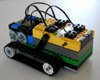
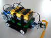
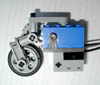
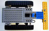
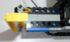
It's fairly easy to augment Baum's Tankbot design to add rotation sensors, one for each motor, so as to implement a pair of velocity sensors. I did it by elongating the Tankbot frame and inserting the rotation sensors between the motors and the RCX, but I'm sure there are plenty of other, more elegant designs. Note that I also raised the RCX so that I could insert the plug for the external AC power adapter; I still haven't bought a set of AA batteries.
 |
 |
 |
| Back | Front | Side |
Rats! I did it again; I started building without thinking carefully about what I was doing. I don't know how I'm going to convince anyone to do otherwise if I don't have the discipline to do it myself: think first and then implement! I'll blame it on the distractions of family visiting for the holidays; every time I get engrossed in working on a robot, there's a party or dinner or some sort of event that I'm supposed to participate in. Well, perhaps the sad tales of my wasting time by forging ahead without thinking will encourage others to think twice.
In experimenting with the modified Tankbot, I encountered a couple of major problems. The first problem was that at low power settings the robot barely moved and at high power settings it moved too quickly for carefully observing its behavior. I attribute the poor performance at low power settings to the observation that the motors have relatively low torque at low speeds despite - possibly partly due to - the gearing and internal flywheel.
The second problem is related and has to do with measuring the velocity. In the design shown above, on a given side, the gear ratio between any pair of the motor, the rotation sensor, and the drive wheel for the tank tread is 1:1. This is partly to blame for the poor performance at low power but it has an additional undesirable effect, namely that the resolution for the rotation sensor is low and hence the accuracy of the velocity measurements is poor. This is the same sort of problem that I had with the cart-and-pole project; you'd think I would have learned something.
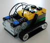
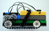
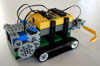
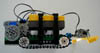
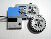
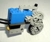
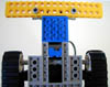
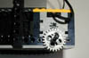
The new design uses four additional gears per side. I didn't want to change the design for the axle layout and all of the simpler designs I could think of had clearance problems with gears hitting the treads or required even more baroque arrangements of idlers and gears. The ratio of the drive motor to the drive wheel is 1:3 so that for every three revolutions of the motor the drive wheel revolves once. The ratio of the drive wheel to the axle of the rotation sensor is 5:2 so that for every two rotations of the drive wheel the axle of the rotation sensor revolves five times. I also added a simple bumper design that I found in the Contructopedia to make it easier to stop the robot during experiments. As in the previous design, the RCX is raised on bricks to allow me to plug in the AC adapter.
 |
 |
 |
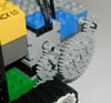 |
| Front | Rear | Side | Detail |
I wrote some code for the PID controller but all I know is that it compiles, loads and the motors turn when I run the program. It didn't seem to perform as I expected when I tried to overload the motors. I added some statements to create a datalog and log the measured velocity and power settings for 100 sample periods but then I had to leave for work. I'm trying to design some introductory labs for the course and refining the code for this PID controller might serve as the basis for a "PID parameter tuning lab" using VanDoren's article for basic reading material and excerpts from the Jones and Flynn book for details on the particular controller implemented in the code. As I was writing this code, I was tempted to write it using two or more tasks for implementing the various component controllers, but I was concerned about timing and ignorant about how NQC handles tasks; I need to find out more about the details of NQC and the RCX firmware on which it depends.
I didn't get back to work on the PID controller code until late last night. In looking at the datalog, it's clear that the power settings immediately max out. This observation also reminded me of something in the VanDoren article concerning the need for "antiwindup protection" in implementing integral controllers. In the controller described in Jones and Flynn [1993], the integral controller is only used to coordinate the two tracks and I never even tested this part of the controller; nevertheless, it's something to think about when I get a chance to debut the code The first thing to look into is adjusting the constants and setting the TARGET_VELOCITY in particular to a reasonable level for some preliminary experiments; once I determine that the controller is actually working I can proceed to tune the parameters. I've been using Mathematica to manipulate the datalog files and graph the data; I think that generating datalogs and using graphing tools to visualize will provide a powerful combination in debugging robots at least in the preliminary stages.
In addition to thinking about a "PID parameter tuning lab", I came up with ideas for three additional labs. The very first lab would be about basic Lego construction and it would cover the following topics: Lego units, beams, frames, bracing, axles, rotational and sliding (prismatic) joints, gears, idlers, mounting motors securely, the advantages and disadvantages of gear reduction, and some basic physics including simple relationships involving torque, speed and power. As a project students would build a solid frame for a robot firetruck of the "hook and ladder" sort with the motor in the "tractor" and an articulated trailor 32cm (or 40 Lego (horizontal) units) long. The emphasis would be on: building a robust engine mount, a solid but easily detachable rotational joint where the tractor and the trailor are joined, and a strong trailer that can support a reasonable load. The readings would include Chapter 4 of [Baum, 2000] and Chapter 4 of [Martin, 1992], "The 6.270 Robot Builder's Guide".
I figure the next lab should cover basic programming in NQC including basic loops, conditionals and assignments, subroutines and macros, multi tasking, alternatives to NQC tasks for multi tasking, simple integer math hacks (what to do when you want real numbers but only have integers), conserving variables, timers and the wait function, and, finally, datalogs and using the display in RCX 2.0. A simple project that makes use of multi tasking might be to use three touch sensors in their simplest (boolean) configuration to write an eight-tone, binary-input piano that has the added ability to lay down a simple "drum track" whose parameters are determined in an initialization phase prior to putting the "keyboard" in play mode. The readings would include Chapter 3 and Appendix D of [Baum, 2000], the online document entitled the "NQC Programmer's Guide: Version 2.2 r1" by Dave Baum. Knudsen [1999] might provide a somewhat different perspective for some students.
The next lab would provide an introduction to sensors. There's so much to do here that I'm not sure where to begin. The right approach is to KISS (keep it simple stupid); sensors are great fun but it's best to approach them with respect. Even the simplest projects involving sensor take care. We might start with software and hardware interfaces for the Lego touch, light and rotation sensors, different modes for touch sensors, calibrating the sensitivity of light sensors for different applications, e.g., sensing light and dark marks on a surface and tracking a bright light in a room with an additional source of (ambient) light, interpreting the output of a rotation sensor for measuring distance and adding gearing to increase sensitivity.
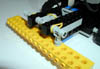
A simple project using the rotation sensor (my current favorite sensor to play with) is to build a measuring device of the sort that navigators and cartographers use to measure distance along an irregular path on a map. I've always wanted one of these so I built a simple one out of Lego. The device has a narrow width wheel attached to a rotation sensor through a gear train that allows you to measure the distance between two points on a map by rolling the device along a path between the two points. RCX 2.0 firmware allows you to display the distance on the LCD. The code is simple but the exercise teaches some basic lessons in using and interpreting sensors. I used centimeters for the basic unit with two decimal places showing on the display even though the resolution of the device doesn't warrant it - one click of the rotation sensor corresponds to a distance of approximately 0.2cm and there are only 16 clicks per rotation. I'd have to add a more complicated gear train to get enough resolution for the device to be useful in plotting routes on maps of the sort you carry with you on automobile trips. Here are some photos of my prototype.
 |
 |
 |
| Left Side | Right Side | Working Pose |
It would be nice to have a lab in which everyone got some experience using a Polaroid sonar sensor as a range finder but there probably isn't time. The RIS light sensor can be almost as subtle to use in cases where you don't have control over ambient light sources. A self calibrating light sensor for Braitenberg-type vehicle would make a very nice project. I'm having fun preparing for this class but a time is rapidly approaching when I'll have to lay aside the robot building to focus on the lectures for my machine learning course. I have learned some lessons that I didn't anticipate.
One of the most important lessons is just how hard it is to interact with the real world. More and better sensors, more accurate and robust effectors, more computational power, and a more sophisticated programming environment - all of these things would help for sure, but the bottom line is that you need to know a lot about the world and about your hardware in order to build and program useful robots. We're not talking about QED (quantum electro dynamics) here; sure, it helps to know some basic introductory physics but a significant part of a good design involves translating common-sense knowledge about the world - albeit hard-won common-sense knowledge - into code fragments - often associated with so-called behaviors - which combine to manifest interesting and useful composite behaviors. The ability to do this well is - like many other kinds of engineering - an art as much as a science and one that seems to be well worth learning.
I read Fred Martin's thesis last night. His thesis questions traditional approaches to training engineers with their (his characterization) emphasis on mathematical modeling and their neglect of hands-on, goal-driven problem solving. I expect he'd be disappointed reading my notebook in which I keep returning to my more-or-less traditional engineering background to explore classic problems, apply standard methods, and consider primarily problems that I know the traditional approaches do well on.
I was particularly taken by his description of two students enrolled in 6.270 taking pains to use feedback control to make their robot drive in a straight line when driving in a straight line wasn't necessarily useful for the task at hand. I admit I'm guilty as charged but I appeal to the mercy of the court and promise to mend my evil ways if only I'm allowed to continue hacking robots. Of course, I expect that even Fred Martin would admit that he's over stating the case somewhat. There is value in knowing about basic techniques such as PID control. And mathematical modeling and simulation are extremely useful in cases where there is a lot at stake and experimentation is either impossible or very costly. However, on one point I agree with Martin one hundred percent: programming robots to interact with the real world and carry out non trivial tasks is extremely difficult and it is easy to get side tracked by what you know or think you know about your hardware and the world with which your hardware (and software) has to interact.
No one made this point more dramatically than Dave Miller (then of the NASA's Jet Propulsion Laboratory and later to found KIPR - the KISS Institute for Practical Robotics) when his Scarecrow (the name is taken from a character in the "Wizard of Oz" who wishes for a brain) robot outperformed other robots (some of them costing hundreds of thousands of dollars more) in the 1992 AAAI Robotics Competition. Scarecrow was constructed from a few dollars worth of parts that anyone could purchase at a hardware store. It was designed to solve the task specified in a particular contest and it exploited every aspect of the contest rules; Dave set out to solve a problem and not to show off some cool hardware or demonstrate some powerful techniques. During the time leading up to the competition no one asked more questions than Dave of the contest organizers regarding the physical details of the contest setting. He knew the value of knowing as much as possible about the problem you're trying to solve.
Pete Bonasso (then of the NASA Johnson Space Center) and I organized the first AAAI Robot Competition (the one that Scarecrow competed in) that was held in San Jose, California in 1992 [Bonasso and Dean, 1997] and so one might assume that I know something about designing robot competitions. That's probably not a good assumption to make but it won't stop me from suggesting a competition for CS148. I don't claim that this competition is particularly original and I could probably have found a perfectly good competition specification produced by someone else; but I think there is some real value in formulating the rules for competitions and thinking carefully about the tradeoffs that go into their specification, so I plan to produce an initial specification myself and then refine that specification with the help of the CS148 students, much as Pete and I did in the months leading up to 1992 AAAI Robot Competition.
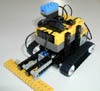
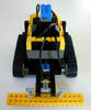
I set out to design both a game and a standard robot competitor. The reason for the standart robot is to encourage students to focus on programming. I imagine teams having two entries: one using the standard hardware but with their specialized software and a second entry with hardware and software designed by the team members. The standard robot competitor, we'll call it a Gamebot, would be a tracked vehicle like Baum's Tankbot. A pair of Gamebots would compete on a playing field similar to the RIS "Test Pad" but with the following pattern (the figure shows two Gamebots, Left and Right; Right is in possession of the ball in Left's territory and heading toward its target goal while Left defends against Right scoring):

There would be a light source mounted over each of the goals; each light would emit a different coded signal (the code implemented by flashing or filtering) to distinguish one from the other. Each Gamebot would have one Light Sensor pointing down to detect the lines on the playing field and a second Light Sensor mounted on the top of the chassis and pointing forward to detect the direction of the Gamebot's goal. That leaves only one input port left. I think a single front mounted bumper attached to a Touch Sensor would suffice and this would be my first choice (KISS). A touch multiplexer such as the one described in [Knudsen, 1999] might offer additional flexibility, but I'll try to design the rules so that the single front mounted bumper is sufficient.
The competition would proceed as follows. One robot is designated as having possession of the ball; the ball doesn't really exist so the robots have to keep track of which robot has the ball. Initial possession is determined by a coin flip. A Gamebot maintains possession of the ball until one of the following events occurs: If the Gamebot in possession of the ball strays outside of the playing field, the robots are stopped, the competitors are set in the middle of the playing field facing one another and on their own territory and therefore facing the goal that each needs to reach in order to score. If the Gamebot penetrates its designated target goal and in doing so it makes an appropriate sound, e.g., ascending arpeggio, then it receives one point and the competitors are reset facing one another and located in the opposition's goal region with the other Gamebot in possession of the ball.
Finally, if the Gamebot in possession of the ball strikes or is struck by the other Gamebot so that its front bump detector is activated while in the other's territory (doesn't matter if the Gamebot in possession of the ball is in its own territory), then both Gamebots must immediately halt (failure to halt within a specified time results in a penalty), the ball changes "hands", and the bots are reset as in the case of leaving the field. Note that it's ok for the Gamebot not in possession of the ball to stray outside the bounds of the playing field.
Other details have to be worked out: For example, what is the length of a game and in what circumstances is the clock stopped or restarted. Also there has to be some protocol for how robots are stopped and started - it may be useful for a robot to retain state information and we may want to allow the robot handler to initialize the robot depending on the situation. It's worth noting that the robots cannot sense one another except by colliding and this halts play if the Gamebot in possession of the ball is in the other Gamebot's territory. We could attach a coded light source to each of the robots but I prefer a simpler competition in which robots only know the location of their opponent when play is started or restarted or when they make contact when the ball carrier is in its own territory.
I think that working out the specifications for the competition is an interesting exercise. It will give students more of an appreciation for what's entailed in setting up a competition like those held in conjunction with the National Conference on AI (AAAI) or the RoboCup competitions the latest of which will be held in August in Seattle, Washington in conjunction with the International Joint Conference on AI (IJCAI). If this competition is to be part of the midterm - and that is what I'm planning at this point - then we should start thinking of a lab (or labs) to introduce the students to various subproblems such as orienting and driving a robot toward a light source and using a downward pointing Light Sensor to "read" and thereby navigate on the playing field.
 |
 |
 |
 |
 |
| Full View | Front View | Bottom View | Downward Light Sensor | Bumper |
 |
 |
|||
| Bumper Side View | Motor Mount |
|
|
|
|
![]()
![]()