 |
 |
 |
 |
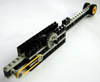
| Left Side | Right Side | Gear Reduction | Full Height |
I opened the Mindstorms Robotics Invention System (RIS) box, took the parts out of the cellophane bags and spread them all over my office floor. I didn't have any AA batteries on hand but I found an AC adapter from an old modem to power the programmable brick (RCX) and a still serviceable 9V battery for the IR tower. Installing the software turned out to be easy. I copied the NQC software from the CD that came with Dave Baum's book onto the disk of an old MacIntosh I happened to have. I also had to copy the latest firmware for the RCX from the RIS CD onto the Mac.
The application MacNQC turned out to be easy to use and I had everything up and communicating with the RCX in no time. I used the Test Panel option under the RCX menu to experiment with the motors and the sensors. I was thinking about building a robot to experiment with the cart-and-pole problem and so I was interested in whether the motors were up to the task. My initial experiments were not terribly encouraging; the motors had a fair bit of torque once they got up to speed but they reversed directions more slowly than I had hoped for.
My goal for today is to produce a preliminary design for the cart and pole problem. In this problem, there is a cart that can move forward and backward on a horizontal surface and there is a pole attached to the top of the cart by a hinge. The pole is free to rotate in the plane determined by gravity and the movement of the cart. The task is to maintain the pole in a vertical position by moving the cart backwards and forwards. The problem is also called the inverted pendulum problem and its solution has many applications including controlling the gimbals that aim the thrusters on missiles - so I guess this is rocket science. I've solved this problem in a variety of guises before but only for simulated systems. Now I'd like to build a device and then see if I can control it using what I've learned over the years on simulated systems.
The design of the cart and the pendulum seem pretty straightforward and the RIS parts seem to offer a wide variety of options. I'm a little worried about the motors as I've heard that they are optimized for particular applications. For cart-and-pole problem, it is important to be able to start, stop and reverse direction quickly and the fact that the motors have an internal flywheel may cause them to perform sluggishly in reversing direction. Playing with the motors a couple of days ago confirmed my suspicions and now I want to run some additional experiments with the motors and write a little program to see how responsive they are.
I also want to experiment with the rotation sensor. The RIS documentation indicates that the rotation sensor divides a full rotation, 360 degrees, into 16 equal intervals which means that the sensor, without additional gearing, has a resolving power of approximately 20 degrees - not nearly enough resolution to balance the pole. I'll have to add some gear reduction to improve the resolution. It may be necessary to add software and hardware to assist in calibrating vertical but, for the time being, I'll just start the robot with the pole vertical and rely on my observation that the rotation sensor is initially set to 0 when the RCX is booted.
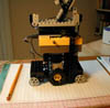
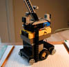
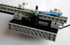
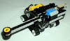
I ended up with only a couple of hours in the morning and a couple more this evening to work on the robot. Construction was trickier than I thought. First I spent a while just familiarizing myself with the different pieces. I spent an hour of so playing with the plates and beams to get an idea of how they worked and how tightly they attached to one another. Then I jumped right in and tried to build the motorized base. My first attempt looked ok at first but then it fell apart when I tried to add to it; I looked through the "Contructopedia" that came with RIS and picked up some clues about how to layer plates and use beams and pins to make stronger structures. I tried forcing some connections but every time I did so it came back to haunt me. Then I figured out the basic measurements and was more careful in my assembly. I took care to make sure that everything lined up exactly. The resulting structures were remarkably strong. My final design has the motor driving two centrally mounted wheels through an axle and reduction gear. There are two additional axles, one at either end of the cart that act as idlers. The motor and driving wheels are mounted in the middle of the cart to keep the center of gravity directly under hinge of the pendulum.
The pendulum is a composite beam on an axle attached to the rotation sensor through reduction gearing. There are two microswitches arranged to sense when the pendulum has fallen too far for the cart to recover; the sensor housings also serve to check the pendulum's fall. The pendulum can move back and forth about 60 degrees. The cart seems to move pretty nimbly when I pulse it with the motor; the whole structure is a little taller than I wanted but it doesn't threaten to topple when I reverse the motor abruptly.
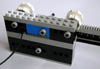
I wrote my first program in NQC for the pole balancing program this morning. In the process, I learned a few things about the touch sensors and encountered the usual aggravating syntax errors but on the whole it was a pretty painless experience. The NQC compiler caught all of the syntax errors and the remaining problems had to do with conceptual errors. I couldn't get it to balance the pole but I think I know why and this afternoon or evening I'll try to modify my code and the hardware to fix some of the problems.
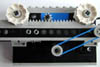
The problems with the hardware have to do primarily with the resolving power of the rotation sensor and the length and weight of the pendulum. The pole is just too short; it's around 25 centimeters long (approximately 10 inches) and I can't balance it for more than a couple of seconds so it doesn't seem reasonable to think that this robot will be able to do so easily. The rotation sensor indicates that the error is zero throughout a range of about 5-10 degrees and often the middle of that range is 5 degrees off vertical. Moreover the error seems to range from -3 to +3.
The problems with the software primarily have to do with controlling the motor and measuring the error. Once I've added gearing to increase the resolving power of the rotation sensor, I want to add code to determine the full range of the possible errors and then add a proportionality constant that can be used to adjust the power to the motor so that the the response is a linear function of the error. If needed, I want to be able to use the full power of the motor.
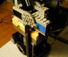
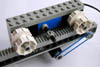
I thought about the resolving power of the rotation sensor a little bit more. In the original design, I used a 24 tooth gear on the shaft of the pendulum hinge and an 8 tooth gear on the rotation sensor for a 3:1 reduction. If I thought for a moment, it would have been clear that this probably wasn't going to be accurate enough. In the new design, I use an additional axle and two pairs of 40 and 8 tooth gears for two 5:1 reductions and a total 25:1 reduction. With no gear reduction, the sensor can be off by as much 22.5 degrees, with 3:1 reduction by as much as 7.5 degrees, and with 25:1 it can resolve angles to a little better than 1 degree. This is a good example of where a little thinking could have saved me a lot of time. The new pole is a little over 42 centimeters long. I can balance it but not well and not for long. I may have to lengthen it yet again. Now I'm going to rewrite the code.
I modified the code and the hardware several times. The final version is a little crufty but clean enough that some else can probably understand it if they're interested. I added weights to the base of the pendulum so that it would be easier to balance; now I can balance the pole fairly easy. I tried variations on both proportional control and bang-bang control. I changed the gearing on the drive motor so that instead of there being a 3:1 reduction there was no reduction at all (both gears have the same number of teeth). I've noticed that it still doesn't calibrate itself as well as I'd like; this may be due to the backlash in the gearing and I'm not sure that there is any value in using greater gear reduction. It may be wishful thinking but a couple of times it seemed to balance the pole for longer than one would expect due to random chance; still, it's not ready for the big top yet. That's about all the time I can spare for this today; playing with these things is definitely addictive.
| |
|
|
|
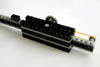
| Left Side | Right Side | Gear Reduction | Full Height |
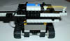
I wanted to design a measuring tape sensor: a sensor that could be used to measure distance accurately. It would have a retractable "tape" that a mobile robot could push up against a solid object and determine the distance from the robot to the object. The tape would be fabricated as a beam that would slide back and forth to extend and retract. It would have a wheel assembly at one end that could be rolled along a surface to follow a wall or determine the shape of a curved object. The length of the tape (or rather the length of its extension beyond its fully retracted position) would be determined using a rotation sensor linked to the tape through rack-and-pinion gearing. A measuring tape sensor could also be used to determine ground truth in calibrating a range-finding sensor such as a sonar. An interesting modification would be to attach the sensor to a rotating platform so the tape could be used as a probe to sense in any direction.
My initial attempt involved trying to use a lego axle as a prismatic (sliding) joint to allow the tape to extend and retract. However, the prismatic joint I built not only slid along the length of the axle but also rotated around the axle. This sort of joint may turn out to be useful for other applications but it had its problems in the case of the measuring tape sensor. I had to attach rack-and-pinion gearing to the tape and so I had to eliminate the rotational degree of freedom. I did this with a pair of rollers; unfortunately, by the time I got all these elements assembled there was too much friction for the tape to retract and extend easily. In addition, the assembly was bulky and, to my mind, inelegant. I took a few pictures of the design and then recycled the lego pieces.
 |
 |
 |
 |
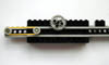
| Slider Joint | Roller Joint | Rear View | Tension Mechanism |
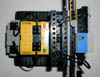
During breakfast I read the chapter in Dave Baum's book on gears and in the section on rack-and-pinion gears I got some ideas for making a simpler measuring tape sensor. The resulting design was much lighter and the tape slides back and forth more smoothly than in my first attempt. I noticed that my assembly time was much faster this time around. Now I can try out several variants very quickly and I have a much better idea of what I can and can't do with the Lego bricks; it took me less than an hour to build the new design and test it.
|
|
|
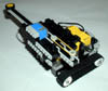
| Front | Rear | Side |
I didn't have time to get back to working on the robot until this evening. I decided to mount the measuring tape sensor on a simple mobile robot and rather than developing my own I used Dave Baum's Tankbot. Assembling the Tankbot from Baum's description was easy. Attaching the measuring tape sensor securely turned out to be more difficult and took most of an hour before I had a satisfactory solution. The final assembly is very strong and could probably sustain a fall of several feet without harm. I don't have time to write any programs for it tonight but I hope to get to it before the rest of the week is out. I think I'll christen the Tankbot with the attached measuring tape sensor as the Measurebot.
|
|
|
|
| Front Left | Front Right | Front Center | Mounting Details |
|
|
|
![]()
![]()