
You "see" colors, geometry, distance, spatial continuity and discontinuity, motion, connectedness and adjacency. These notions are built into the ways in which you experience and think about the world. You interpret the information returned to your senses through a rich model of the world. The robots you build will not have such a model unless you supply it. Moreover the simple touch, light and rotation sensors that your robots will use to sense the world are very different from your tactile, visual and proprioceptive sensors and, hence, your intuitions and models may not be appropriate to apply to interpreting Lego sensors.
The sensors designed for the Lego Mindstorms RIS are fairly well behaved as sensors go. The Lego engineers did a good job of trading accuracy for simplicity and reliability of use. Of course, some would say that sensing problems are rarely due to the sensors themselves; they arise primarily due to problems in interpreting the data returned by sensors. Others might quip that a good sensor should be designed to return unambiguous data, but that misses the point. Sensing is all about measuring physical quantities often termed signals (e.g., reflected acoustic energy in the case of sonar) and interpreting these measurements in order to draw conclusions about other physical quantities (e.g., the distance to nearby physical objects that might constitute obstacles to a mobile robot). Any signal that obscures the signal you want to observe is referred to as noise. Ambiguity refers to there being more than one interpretation of a given signal. Ambiguity and noise are just part of the sensing game.
Consider the Lego touch sensor; this device consists of nothing more than a contact switch held open with a spring and wired in series with a load resistor.

Simple mechanical switches such as the Lego touch sensor tend to bounce when pressed. The signal we want to detect corresponds to distinct pressings of the switch; the bounces that arise as a consequence of mechanical and electrical chattering of the contacts are considered noise. Click on the graphic below to learn more about bouncing in mechanical switches.
In order to avoid counting the bounces when a switch is pressed, e.g., on a computer keyboard, mechanical switches are generally debounced either by adding additional circuitry (e.g., a capacitor across the switch contacts) or by employing some sort of filtering subroutine which, when it detects a voltage transition, it ignores subsequent transitions for a short period following the initial transition assuming that the later transitions are due to bounces and not distinct pressing events. The RCX and legOS software do a good job of conditioning touch sensors so that they are reasonably well behaved.
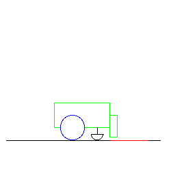
The Lego light sensor is also well behaved as such sensors go but the physics of sensing light levels is much more complicated and not surprisingly so is the task of interpreting the values returned by light sensors. Let's reconsider the light-following robot that we demonstrated during the lecture on Braitenberg's vehicles. That robot made use of a Lego light sensor to sense the light produced by a flashlight and reflected off the carpet; the robot used a light sensor aimed at the floor to follow the spot of light cast by the flashlight. The Lego light sensor can also be used without an external source of light as it has an LED that provides a source of light. Using it's self-contained light source, a downward pointing Lego light sensor can be used to distinguish between the colors painted on the horizontal surface of a playing field designed for robot competition. Variations on this basic idea give rise to robots that read marks on horizontal surfaces for a variety of applications from game playing and line following to object recognition. This wide variety of applications makes the Lego light sensor one of the most interesting to work with. In picking projects, it's more productive to think first in terms of what you can do with the available sensors rather than start with an application and work backwards to how the available sensors would support that application.

|
|
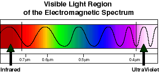
In order to understand how the Lego light sensor works we have to consider how light of various wavelengths is transmitted, absorbed, reflected and converted into other forms of energy. Humans see in the the so-called visible light region of the electromagnetic spectrum. Click on the graphic below to learn more about the electromagnetic spectrum.
 |
The phototransistor used in the Lego light sensor appears to have its peak sensitivity at around 800nm. Here is a graph of the sensitivity of a similar phototransistor as a function of wavelength measured in nanometers (1000 nanometers = 1 micrometer (micron) so that 800nm = .8mm)
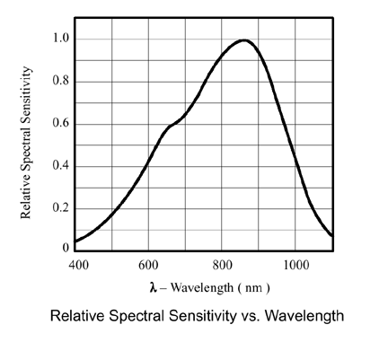
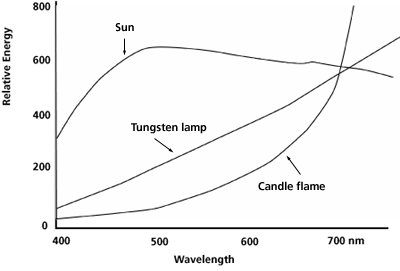
This means the peak sensitivity for the Lego light sensor is in the infrared end of the spectrum. The human body radiates most strongly in the infrared range around 10 microns while the portion of the infrared spectrum used by TV remote control devices and the RCX tower is called near infrared (longer wave lengths) and does not feel warm at all. Human daylight vision works best in the blue-green region of the spectrum where the sun's energy is at a maximum. The light from a flashlight bulb is typically broad spectrum and tungsten bulbs tend toward a maximum at the red end of the spectrum.
The issue of the frequency response of sensors and the frequency spectrum of sources is complicated still further by the fact that in many cases we're interested in the light reflected from surfaces that are not perfectly reflective (they absorb some frequencies and reflect others) and for which the angle of incidence is often different than the angle of reflection. Some materials tend to behave like mirrors (they are said to be specular) and others tend to scatter light in all directions (they are said to be diffuse). Click on the following graphic to learn more about the physics of reflected light.
 |
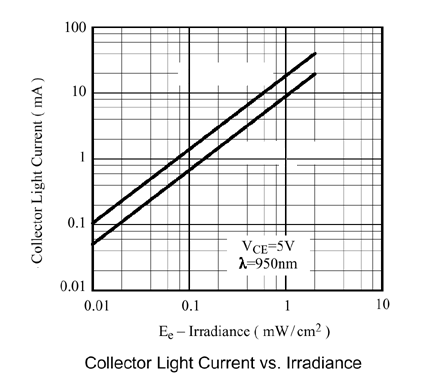
There are other complications that concern the characteristics of the phototransistor such as its response (current) as a function of the light falling on the surface of the sensor (irradiance). However, you are largely sheltered from these complications by the hardware and software of the RCX.
There are some other physical characteristics of the Lego light sensor that you should be aware of. The phototransistor used in the Lego sensor is enclosed in a plastic dome or lens which gives it a wide angular view. If you want to use the sensor as a directional finder you will probably want to use a tube or an arrangement of Lego bricks to restrict the angle of light falling on the sensor. This can be important when, for example, you want to use the light sensor to aim a robot toward a light source.
Here is the circuitry for the Lego light sensor. We're not going to go into details but there are a few things worth pointing out. The Lego light sensor is a powered sensor; it requires power to run its circuitry. Since Lego sensors only have two wires connecting them to the RCX these two wires must be used both to send power to and receive signals from the sensor. Polarity is also a problem given that the Lego connectors allow sensors (and motors) to be attached in any one of four different orientations. These complications are handled by a combination of a special circuit comprised of a diode bridge and a storage capacitor and special software that rapidly switches between driving the circuitry and reading off the sensed values. The capacitor stores enough power so that the circuit continues to function when the sensor is being read. The Lego light sensor is said to be an active sensor in that it not only senses light but it also provides a source of light, i.e., it does not rely passively on a source of light. Click on the circuit diagram below to learn more about the Lego light sensor.
The Lego rotation sensor uses two infra-red-LED phototransistor pairs called photo interruptors and a rotating axle with four blades to get 16 steps per turn of the axle plus directional information. The photo interruptors and the four blades are arranged so that at any time the voltage drop across output of the circuit is one of 1.3V, 3.3V, 2.0V and 4.5V thereby providing the necessary resolution. Click on the following image to learn more about the Lego rotation sensor.
The most difficult part of using the rotation sensor involves gearing the axle that turns the blades in the sensor so that you can obtain the necessary precision or resolution. 360 degrees divided by 16 is 22.5 degrees. Suppose you have an application in which one degree of error is crucial? A classic application for rotation sensors is the so-called inverted pendulum problem which is roughly equivalent to balancing a stick on the palm of your hand. Mathematically it is equivalent to the problem of backing up a tractor trailer without jack knifing the rig or keeping a missile balanced on the thrust of its rocket motors. For these applications, relatively high precision is required in measuring the angle of the stick with respect to horizontal, the angle of the trailer with respect to the tractor or the angle of the missile with respect to its intended direction of travel.
Michael Gasperi's RXC sensor input web page is a good source for information on Lego sensors. Of particular interest are Gasperi's articles on the Lego light sensor and the Lego rotation sensor. If you're into building your own sensors, Gasperi's contribution to the book, "Extreme Mindstorms" [Baum et al., 2000], is a great place to start. Martin [2001] is also full of ideas about building sensors. See Page 118 Section 3.6 entitled "Reflective Optosensors" of [Martin, 2001] for more on light sensors. You might also check out my notes on sensors from last year's class.
Sensing is performed to gain information about the world. Often, the programmer has in mind some desired state of the world and wants to reduce the difference (or error) between the desired and the actual state of the world so as to eventually achieve the desired state. In cases such as designing a cruise control for an automobile, this view of control is easy to realize in a feedback controller. In other cases such as cleaning an office or delivering mail, the view is less useful. Nevertheless, simple feedback systems figure prominently in the low-level control components of more complicated systems and are worth understanding. The follow diagram (adapted from [Martin, 2001]) illustrates the basic components of feedback control.
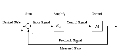
In the simplest version of feedback control called proportional control the controller computes the error (the difference between the desired state of the world or target and the measured state of the world or feedback signal), amplifies this error signal by multiplying it times a constant KP (the constant of proportionality also known as the proportional gain) which is then used to adjust some parameter of the controller. In the case of a automobile cruise control, the target is your desired speed, the error is the difference between your current speed and your desired speed, and the adjusted parameter is the angle of the accelerator pedal or the rate that fuel is being pumped to the engine. By increasing the gain, you can obtain a more responsive controller but often at the expense of overshoot (when you zip right past your target state) and oscillation (when you repeatedly zip back and forth past your target state). Control engineers try to adjust the gain to obtain a reasonable tradeoff between responsiveness on the one hand and overshoot and oscillation on the other.
There are an amazing number of devices that can be controlled by some form of proportional control. In some cases however, there are refinements that can either extend or improve the application of this method. If you compute the "instantaneous" change (or derivative) in the error you can get some idea of how quickly the relevant state of the world is changing. As you get close to the desired state of the world you probably don't want to be changing too quickly or you're likely to overshoot. If the relevant state of the world is the velocity of a car, then its derivative is the acceleration of the car; as you near the desired velocity you don't want to be accelerating. Often it makes sense to add another component to a proportional controller that accounts for the derivative term. You can use the derivative term subtractively to reduce overshoot in the case of a cruise control system.
There are also situations in which you want to amplify your response based on the derivative term. If the relevant state of the world is the angle of a stick with respect to the horizontal as in the case of the inverted pendulum problem, then its derivative is the angular velocity. If the stick is falling it matters whether it is falling slowly or it is falling quickly. The inverted pendulum problem is actually a rather difficult control problem (at least when compared with, say, the cruise control problem). If you're interested, you can learn more about control problems and their solution by reading Chapter 2 and Chapter 4 of [Dean and Wellman, 1991].
As long as we looking at the derivative of the error we might as well \ consider taking a look at the integral of the error as well. Typically we'll only be interested in the integral over some recent interval. What might the integral of the error tell us? Suppose that the integral is zero or nearly so; under what circumstances might this happen? For completeness, here is the general form of a proportional-integral-derivative (PID) controller.
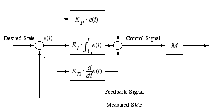
PID controllers are used in a wide variety of applications. Often as not a control system will be composed of several PID controllers controlling different parameters of the system. Simple, slow moving robots of the sort you'll be working with generally don't require the use of sophisticated control techniques; however, you'll want the basics of PID control in your bag of tricks. Jones and Flynn [1993] provide a nice example of a controller for a tracked mobile robot that combines two PID controllers using only proportional components (velocity controllers, one for each track) and one PID controller with only an integral component (a distance-traveled (the integral of velocity) controller which ensures that each track turns the same number of turns and hence the robot drives approximately straight).
See Page 179 Section 5.2 of [Martin, 2001] entitled "Proportional-Derivative Control" for a discussion wall following using the proportional and derivative components of PID control and Page 286 Section 6.5 entitled "Line Following as a Reference Activity" for an application to following a line printed on a horizontal surface. You might also look at my notes on proportional integral derivative control from last year's class which includes a pointer to an article by Vance J. VanDoren in the March 1998 issue of Control Engineering and other references.

| [Baum et al., 2000] | Baum, D., Gasperi, M., Hempel, R., Villa, L.Extreme Mindstorms: An Advanced Guide to Lego Mindstorms, Apress, 2000. |
| [Dean and Wellman, 1991] | Dean, T., Wellman, M., Planning and Control, Morgan and Kaufmann, 1991. |
| [Jones and Flynn, 1993] | Jones, J.L., Flynn, A.M., Mobile Robots: Inspiration to Implementation, A K Peters, 1993. |
| [Martin, 2001] | Martin, F., Robotic Explorations: A Hands-On Introduction to Engineering, Prentice-Hall, 2001. |
| [VanDoren, 1998] | V.J. VanDoren, "Tuning Fundamentals: Basics of Proportional-Integral-Derivative Control", Control Engineering, March, 1998. |