Introduction
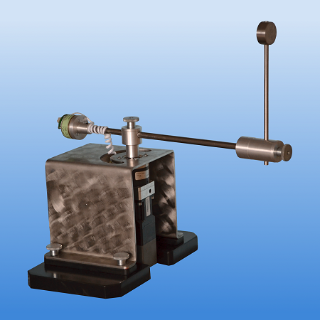
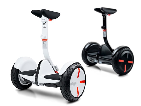
For my final project I be designing and controlling an inverted pendulum. In general, an inverted pendulum is a mass on a stick that can freely pivot on a single axis. The goal of controlling it is to balance it with some kind of actuator so that it stays in the upright position. Early in the design process I planned on controlling a Segway robot, but because of cost limitations, I settled on controlling another form of inverted pendulum commonly known as the Furuta Pendulum. The Furuta Pendulum is named after its creator, Katsuhisa Furuta, and exhibits an inverted pendulum attached perpendicularly to an actuated, rotational base. At a minimum, I am hoping to control it through a PID feedback controller that receives sensor readings from a rotary encoder. If time permits, I would also like to make it remote controlled, explore different controllers, and/or design a “swing up” initialization sequence where the pendulum can swing itself up from the resting position by itself.
 Various types of Inverted Pendulums
Mechanical Design
 Side and Front View
The rotating arm and the pendulum are both made of lengths of scrap wood I found in the BDW. The arm is actuated by a 12V DC motor. The pendulum is connected to the arm by a rotary encoder that can pivot freely with minimal fiction. The base holding the motor (not shown) is also made from scrap parts from the BDW, but with heavy aluminum extrusions to prevent vibrations of the actuators from affecting the controller.
Electronic Parts and Connections
 Connections for electronics
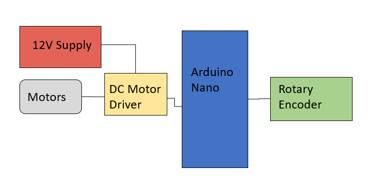
The PID controller will be implemented on an Arduino nano, which will also receive sensor readings from the encoder and control the DC motors. A 12V DC supply will power the motor and the arduino receives 5V and command signals from the USB. The connections for all the parts are relatively simple and is outlined in the figure above.
PID Controller (Balancing)
 PID Overview
To balance the pendulum in the upright position, I will be using a PID controller. Here, the setpoint will be 0 (vertical position), the error will be the difference between the current angle measured from the rotary encoder and the setpoint, and the output will be a pwm signal from 0 to 255 that will control the DC motor.
P Controller
The first step in tuning a PID controller is setting the Ki and Kd values to 0 and only focusing on the Kp value. This will effectively give a P Controller. I increased the value of Kp until the pendulum was able hold the pendulum upright for a few seconds while rapidly oscillating. The final value I chose was Kp = 20.
PI Controller
One major flaw of the P controller was that it would begin to lean to one side and eventually begin to plummet down. Adding the integral term will stop the pendulum from over extending on either side of the axis. If the pendulum starts to lean one way, the error on that side will begin to accumulate and the integral term of the controller will slowly add more force over time to lean in the other direction. Having to high of Ki will lead to overshoot as well, so I increased Ki until the overshoot from the integral term began to affect the stability. The final value was Ki = 0.00016.
PID Controller
Finally, to decrease the rapid oscillation, we can introduce the derivative term. The derivative term will decrease the output if the pendulum is moving towards the setpoint and increase the output if the pendulum is moving away. In effect, we will see a "dampening" effect when the pendulum is moving to the vertical position. This will decrease overshoot and give us a smoother and reliable controller. I increased te Kd term until the stabilizing was being affected, resulting in Kd = 100000.
Swing-Up (Energy Control)
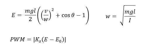
Next, I wanted to implement a separate controller that will automatically swing the pendulum from any position to somewhere near the upright position. Here, I chose to use energy control. This does not replace the PID controller, but helps move the pendulum close to the set point so that the PID can stabilize the pendulum in finer detail. In essence, we want to add energy to the system via the motor until it reaches the energy state of the upright position. To do so, we need a way to calculate the current energy of the system. The current energy will have components from the gravitational potential energy (angle of the pendulum) and its current kinetic energy (angular velocity), both of which we can calculate from the rotary encoder. In the equation above, E is the total energy, m is the mass of the pendulum, g is the gravitational constant, l is the length from the pendulum's CoM to the pivot point, v is the angular velocity, theta is the angular position, and I is the moment of inertia of the pendulum around the pivot point. This gives us a minimum energy when x=180 and v=0 of -mgl and a maximum (desired, upright position) energy when x=0 and v=0 of 0. We then send a pwm signal that is proportional to the energy difference between the current energy state and the desired state. The magnitude of the pwm signal is also above. Ks is the tuning parameter to scale the needed energy to an acceptable pwm value. The final value of Ks was 2700.
Combining PID and Energy Controller.

Once the PID and Energy controllers were both working, I could combine them together. The goal for combining the controllers is to make the pendulum automatically swing up after initialization and begin balancing. If some external force pushes the pendulum down, the swing-up controller will activate again and return the pendulum back near the upright position. The swing up controller is clearly able to swing the pendulum to the upright position. However, a problem occurs in making the PID catch the pendulum when it nears the top. If the pendulum has too high of a velocity, it may overshoot the top. The optimal operation of the balancing PID is 10 degrees around the set point. Overshooting the setpoint will cause the PID to react with large oscillations that will eventually cause the pendulum to fall again. To remedy this, I set up and intermediate region between the swing-up and balancing zone just to "catch" the swing up. When the pendulum is between 10 and 45 degrees on either side, a second PID controller with high Kd will first be executed. The reasoning here is to attempt to dampen the pendulum's movement after the swing-up phase. Once the pendulum reaches the optimal operation range for the stabilizing PID, it will kick in and begin balancing the pendulum.
Future Improvements
Fixed frequency for PID Evaluation: Currently, the PID is calculated in every loop, but adding more calculations in the loop will change the PID evaluation frequency. This will cause the pendulum to behave differently. Printing data will be very helpful for fine tuning parameters, but printing is a time consuming task and will change the behavior of the system.
Increasing PWM resolution: Currently my output values are integers between 0-255. Increasing the PWM resolution (with fast_pwm) will give me a larger range of output.
Predictive modeling: Using PID was not a very optimal way of controlling the behavior. Better to use a control system explicitly based on the dynamics of the system. Many examples online used an LQR controller to make it more robust.
Remove encoder wire: The encoder wire restricts the pendulum's full range of motion.
Timeline and Progress
-
Hardware Budget
1 Ocotber, 2019List out all items and create detailed hardware budget
-
Web description
22 Ocotber, 2019Create project description website outlining project design and progress
-
Implementation status report
26 November, 2019Finish builing the penedulum and implement PID controller on the arduino. Test approximated parameters and tune.
-
Project Presentations
10 December, 2019At minimum allow pendulum to stand upright. Add energy control if time permits.
-
Project Hand in
12 Decemeber, 2019Hand in Project