Building a five-stage pipelined CPU in Ripes
Intro
We will be working in the src/processors/CS1952y/five_stage_cpu directory. As for the single-stage notes, the code for the intermediate steps is given in the subdirectories.
Step 1: Adding pipeline registers
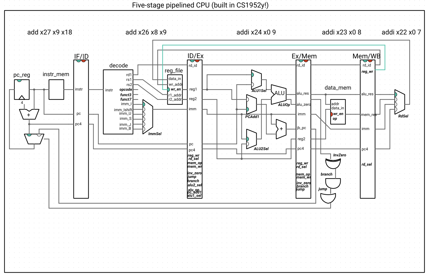
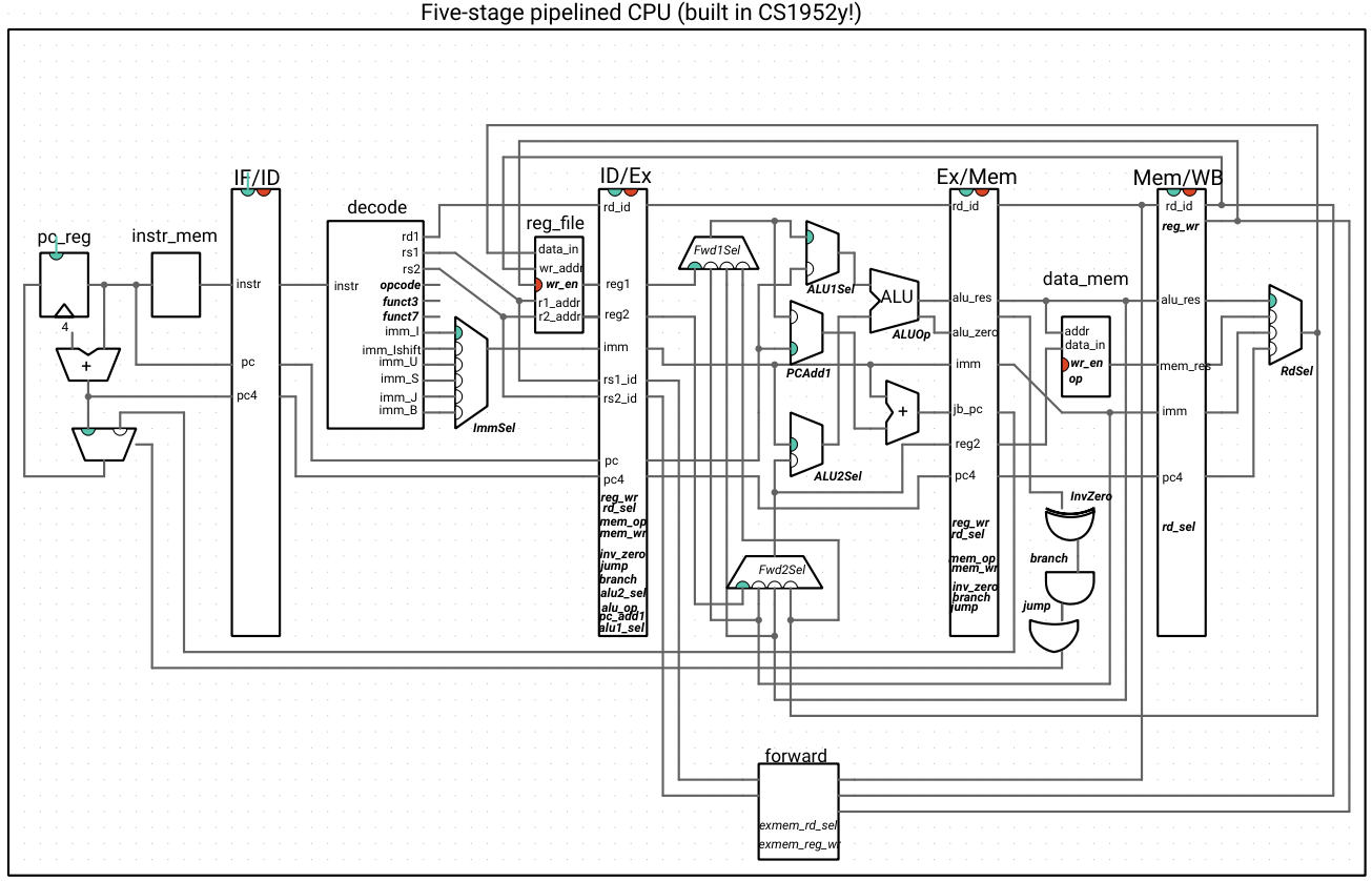
In a pipeline, an instruction is broken up into stages. Our stages will follow the P&H breakdown of Instruction Fetch (IF), Instruction Decode (ID), Execute (Ex), Memory (Mem), and Writeback (WB). An instruction will now take five clock cycles to execute, one for each stage. To marshall the correct data through the pipeline, we need to put registers between each of the stages. Note that we also need to pass along any control signals that are needed for subsequent cycles. Here, we list the signals that each stage needs from the previous stages. In parentheses, we indicate the stage where the signal originated, meaning that we will need to pass that signal through any intermediate preceeding stages, as well.
As you read through this list, pause and think to yourself about why a specific stage needs a specific piece of data (for example, the Ex stage needs the PC because the AUIPC instruction uses the ALU and because the new PC for jumps/branches will be computed in this stage). Another way to verify this is by looking at the diagram above. For example, the Mem stage needs the value of R2 because the data_mem component from that stage takes that data in as an input.
The ID stage needs:
- The instruction (IF)
The Ex stage needs:
- The PC (IF)
- The value of R1 (ID)
- The value of R2 (ID)
- The immediate (ID)
- The control signals ALU1Sel, ALU2Sel, and ALUOp (ID)
This stage will hold the adder that computes the new PC for any jump/branch, using the old PC or R1 and the immediate, so it also neeeds: -The control signal PCAdd1 (ID)
The Mem stage needs:
- The result of the ALU (Ex)
- The value of R2 (ID)
- The control signals MemWr and MemOp (ID)
To route back to the mux that selects between PC+4 and any newly computed PC, this stage also needs:
- The result of the adder that computes the new PC (Ex)
- The zero signal of the ALU (Ex)
- The control signals jump, branch, and InvZero (ID)
The WB stage needs:
- The result of the ALU (Ex)
- The immediate (ID)
- The value of PC + 4 (IF)
- The result of the memory read (Mem)
- The ID of the Rd register (ID)
- The control signals RdSel and RegWr (ID)
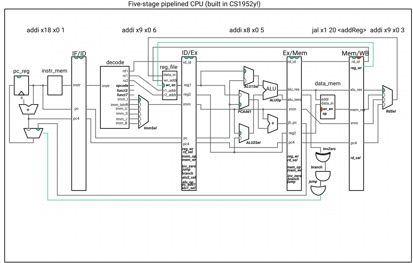
For now, we are ignoring any data and control hazards. We still include the branching/jumping and writeback circuitry for when we address these hazards, but we cannot safely run writeback and control instructions that depend on instructions still in the pipeline.
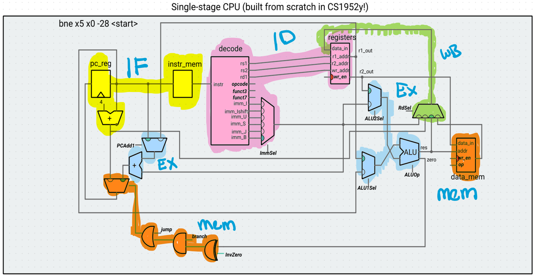
As before, to reduce visual clutter, we omit control signal wires and use bolded and italicized text to indicate where the control signals are used. The exception is reg_wr, which we explicitly show as going “back” to the register file (because the write functionality of the register file occurs in the writeback stage). Any control signal used in a specific pipeline stage comes from the preceding register (for example, ALU1Sel comes from the ID/Ex register, while RdSel comes from the Mem/WB register).
Assessing the pipeline
Let’s run this very simple program, which does not have any data or control hazards (that is, the result for an instruction X has already passed the writeback stage before any instruction Y that requires the result of X is issued) for our pipeline:
addi s0 x0 1
addi s1 x0 2
addi s2 x0 3
addi s3 x0 4
addi s4 x0 5
addi s5 x0 6
addi s6 x0 7
addi s7 x0 8
addi s8 x0 9
add s10 s0 s1
add s11 s1 s2
add t0 s2 s3
add t1 s3 s4
add t2 s4 s5
add t3 s5 s6
add t4 s6 s7
add t5 s7 s8
add t6 s10 s11
The value of t6 at the end of this program should be 8 ((1 + 2) + (2 + 3)), which is the case for both the single-stage and 5-stage processors. The CPI (cycles per instruction) for the 5-stage pipeline is 1.22 (because of the extra cycles needed to “warm up” the pipeline). This seems worse than the single-stage processor, which always has a CPI of 1. However, the clock period would be substantially smaller, leading to an execution time speedup.
Step 2: Handling control hazards
Whenever our single-stage CPU had to jump or branch, we were guaranteed that the PC would get set to the correct address on the next cycle. This is because all computations happened in one cycle, including the arithmetic to compute the new PC address and the logic to determine what value should go into the PC register for the next cycle. In our five-stage pipelined processor, the arithmetic occurs in the Ex stage and the branch/jump logic occurs in the Mem stage, while the IF stage fetches a new instruction on every cycle. We’ll explore the consequences of this now.
Observing a control hazard
Consider the following code:
addi s0 x0 1
addi s1 x0 3
jal addReg
addi s0 x0 5 # should be unreachable
addi s1 x0 6 # should be unreachable
addi s2 x0 1
addi s3 x0 1
addReg:
addi s2 x0 1
addi s3 x0 1
addi s4 s0 9 # should be 10
addi s5 s1 9 s3 # should be 12
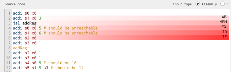
What values do s4 and s5 have at the end of this program? Stepping through the pipeline, when does the PC get updated with the jump address?
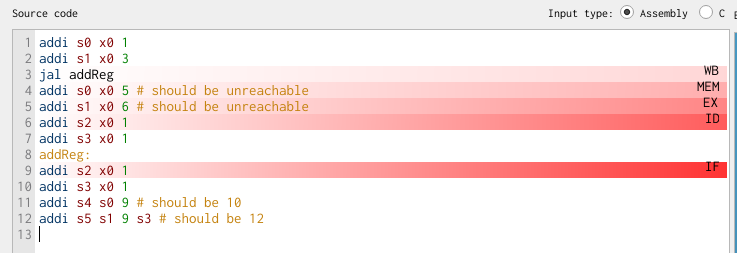
This is where different views in Ripes are helpful. In the processor view, we see that the output of the branch/jump gate logic in the Mem stage is high only when the jal instruction reaches the Mem stage:
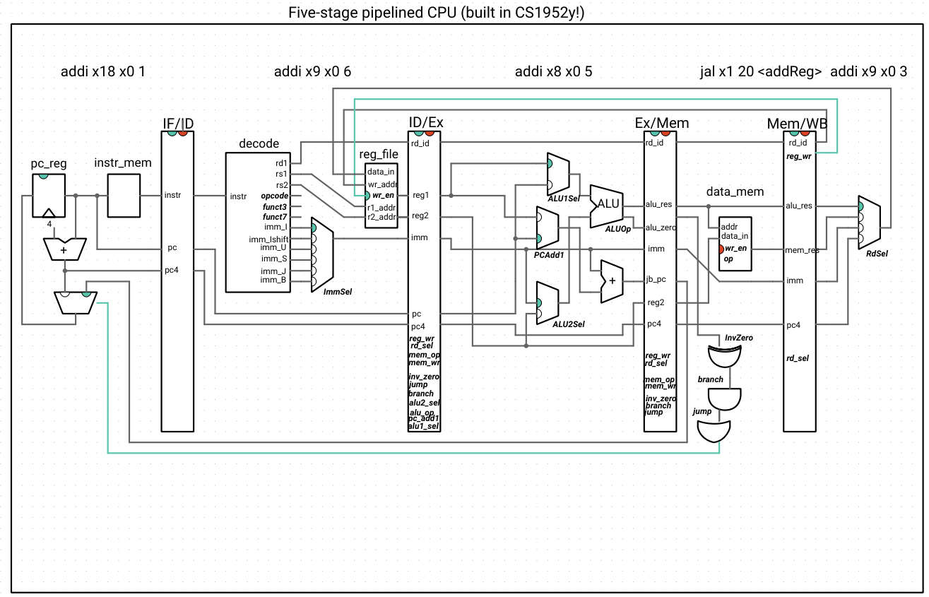
In the editor view, we can see that the subsequent three instructions are in the pipeline already:
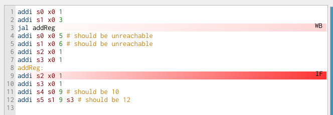
If we advance by one clock cycle, only then does the instruction at the addReg label enter the pipeline at the IF stage (skipping over the instruction on line 7 only, when we want our execution to skip lines 4-6 as well):
Flushing the pipeline
We can see that the pipeline continues fetching subsequent instructions while the jump address (or branch address and decision!) are being computed. For this reason, the RISC-V reference manual recommends that code be optimized so that branches are unlikely to be taken. If the branch does get taken, we need some way of flushing the instructions that were in the pipeline between the branch instruction and the IF stage where the PC changes to the branch destination address. For simplicity’s sake, we will do the same with jumps – since jump instructions rely on the Ex stage to compute the new PC, we won’t bother distinguishing between when we deal with branches and jumps. Indeed, we will rely on the input to the mux that selects the new PC (the output of the OR gate in the Mem stage) to detect when we need to flush the pipeline.
How do we flush the pipeline? We will rely on the enable and clear control signals of the pipeline registers (they are indicated at the top of each register – so far, enable has always been high, and clear has always been low). For a clocked register, driving the enable signal low means the register is unresponsive to the input (that is, hangs on to its previous internal state). Typically, we drive the enable signal low to keep the register from changing its output for one or more clock cycles. Driving the clear signal high means the register produces a 0 for all of its outputs. In particular, this means that the reg_wr and mem_wr signals would change to 0 (and get passed along the rest of the pipeline as such), meaning that there are no permanent side effects (register or memory writes) where an instruction got cleared.
Pipeline diagram for our control hazard
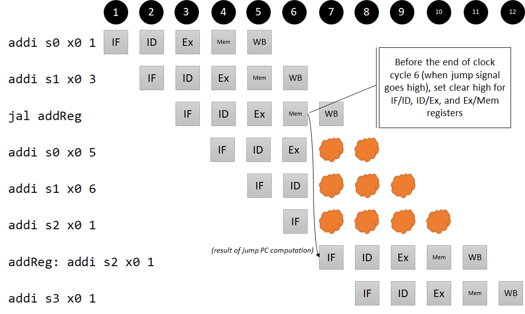
Because we see that three instructions are loaded into the pipeline that shouldn’t be, we need to clear IF/ID, ID/Ex, and Ex/Mem registers. We don’t need a new component (for now) – we can just connect the output of the jump-or-branch or gate to these signals! To avoid clutter, we don’t draw these wires directly, but notice how the clear indicators change to high if and only if the jump or branch logic is high:
j_or_b->out >> ifid_reg->clear; // same for idex_reg, exmem_reg
Now we see that, when the jal reaches the mem stage, all of the clear signals in the hazard unit are high, and in the next cycle, the pipeline is flushed, with the instruction at the addReg label in the IF stage:
You might be thinking that jump and branch instructions almost cancel out the whole point of pipelining, since flushing the pipeline means that portions of the CPU aren’t doing meaningful work until the new instruction is fetched. You would be right! It turns out, branching is a problem that computer architects have spent years thinking about. We’ll revisit strategies for dealing with this, such as branch prediction, later in the semester. For now, we want to avoid inserting periods of idleness into our processor as much as possible, which leads to our discussion of forwarding.
Step 3: Handling data hazards using forwarding
A data hazard occurs when an instruction needs data that hasn’t been written back to the register file yet. We could handle data hazards similarly to how we handle control hazards, by causing the pipeline to be idle until the dependent computation reaches the Writeback stage (this would be called a “stall” or “bubble” rather than a “flush,” since we’d be inserting nops in between instructions instead of clearing existing instructions). It turns out that we’ll have to do this sometimes, but we can avoid idleness in many circumstances using a strategy called forwarding, where we simply bypass the register file and move data to the correct place the moment it is available. For an instruction that uses the ALU, the result is available at the end of the Ex stage, and for an instruction that uses data memory, the result is available at the end of the Mem stage.
Let’s examine the following code snippets, which have Ex/Ex and Mem/Ex hazards similar to those described in P&H 4.7. In the following examples, we include nops so that we don’t have to worry about hazards when initializing registers, and label the actual hazards using comments.
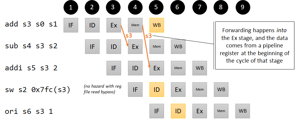
Ex/Ex hazards
addi s0 x0 3
addi s1 x0 5
addi s2 x0 7
nop
nop
add s3 s0 s1 # s3 = 3 + 5 = 8
sub s4 s3 s2 # s4 = 8 - 7 = 1; s3 dependency, 1 instruction ago
addi s5 s3 2 # s5 = 8 + 2 = 10; s3 dependency, 2 instructions ago
sw s2 0x7fc(s3) # 7 @ address 0x00000804 s3 dependency, 3 instructions ago
ori s6 s3 1 # s6 = 8 | 1 = 9; no dependency
Notice that, while sw is a memory instruction, the dependency in this case is in the execution stage, since the ALU needs the value of s3 in order to perform the correct address computation. Run on a single-cycle processor, the result is correct (all registers have the correct values, and the value at memory address 12 is 7), but on our five-stage pipeline, it is incorrect.
We can immediately get rid of the add/sw dependency by setting the “readBypass” flag of the register file to true (this is effectively the register file design decision that P&H talks about, where the write to the register file is done in the first half of a clock cycle and the read is done in the second half, hence making written values available to reads of the same register on the same clock cycle). The other dependencies we will get rid of using forwarding.
Pipeline diagram for our Ex/Ex hazard
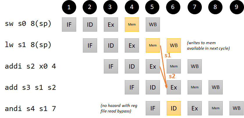
Mem/Ex hazards:
Note that there is another version of the Mem/Ex hazard that cannot be resolved by forwarding. We ignore it for now and revisit it later.
addi s0 x0 11
nop
nop
sw s0 8(sp)
lw s1 8(sp) # s1 = 11; no dependency; memory updates immediately in mem stage
addi s2 x0 4 # s2 = 4; no dependency
add s3 s1 s2 # s3 = 11 + 4 = 15; s1 dependency 2 instructions ago
andi s4 s1 7 # s4 = 11 | 7 = 3; no dependency (with read bypass)
Pipeline diagram for our Mem/Ex hazard
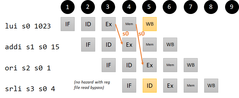
LUI hazard
The data from a writeback to the destination register can come from four places: the ALU, data memory, the link register computation (PC+4), and the immediate (for LUI). This won’t add much complexity to our forwarding logic, but we include a code example just so we can use it to check that our forwarding unit is working correctly. We do not worry about an example where PC+4 needs to be written back to a register, because that only happens in the case of JAL and JALR, and our implementation in Step 2 ensures that the values will be written back before any other instructions need these registers.
lui s0 1023 # s0 = 4190208 (0x003ff000)
addi s1 s0 15 # s1 = 4190223 (0x003ff00f); s0 dependency 1 instruction ago
ori s2 s0 1 # s2 = 4190209 (0x003ff001); s0 dependency 2 instructions ago
srli s3 s0 4 # s3 = 261888 (0x0003ff00); no dependency (with read bypass)
Pipeline diagram for our LUI hazard
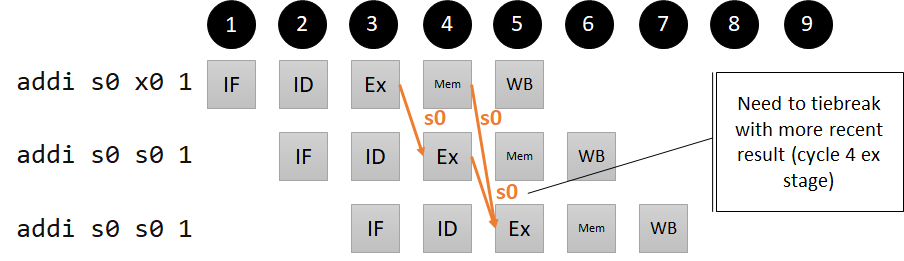
Consecutive Ex/Ex/Ex hazards
We need to account for the situation where the same register is used in subsequent ALU operations, such as:
addi s0 x0 1
addi s0 s0 1
addi s0 s0 1
In this case, we need the third instruction to see the latest value of s0, so our forwarding unit needs to prioritize which value it forwards (when the third instruction reaches the Ex stage, it should be getting the forwarded value of s0 from the Mem stage, not the WB stage, to accomplish this).
Pipeline diagram for our Ex/Ex/Ex hazard
Implementing the forwarding unit
Using the hazard definitions to guide us, we build up the forwarding unit logic. This logic hinges on checking the address of rd in the Ex/Mem stages and comparing it to the Rs addresses in the ID stage. Remember that the register file takes care to enforce that x0 is a read-only register, so we need to make sure we are not forwarding any values that would be “written” to x0.
First, we start with forwarding an ALU result which is needed in the subsequent ALU cycle (Ex/Ex dependency from 1 instruction ago). We also have to account for the LUI dependency from 1 instruction ago:
if (idex.rs[1/2]_id == exmem.rd_id) and
  (exmem.reg_wr) and
  (exmem.rd_id != 0):
    if (exmem.rd_sel == IMM):
        forward exmem.imm to ALU[1/2]Sel input 1
    else:
        forward exmem.alu_res to ALU[1/2]Sel input 1
If the rs register in question is rs1, we also need to forward the value to the PCAdd1 mux, and if it is rs2, we also need to forward the value to exmem.reg2 – we leave this implicit in these explanations, but are sure to wire it up in our forwarding implementation.
Next, we start with forwarding an ALU or Mem result which is needed two cycles later in the ALU (Ex/Ex dependency from 2 instructions ago, or Mem/Ex dependency from 2 instructions ago, or LUI dependency from 2 instructions ago):
if (idex.rs[1/2]_id == memwb.rd_id) and
  (memwb.reg_wr) and
  (memwb.rd_id != 0):
    forward RdSel output to ALU[1/2]Sel input 1
We are forwarding the RdSel output instead of the individual signals from the Mem/WB pipeline register because we assume multiplexers (such as the RdSel mux) are fast, and it means we only have to forward one output instead of three.
We remember that we prioritize the latest result in the case of consecutive Ex/Ex/Ex hazards, so the first piece of logic (single-cycle dependency) takes precendence over the second piece of logic (two-cycle dependency).
These expressions show that our forwarding unit needs to take in the following inputs:
- idex.rs[1/2]_id (also needs to be added to the idex pipeline register)
- exmem.rd_id
- exmem.reg_wr
- exmem.rd_sel
- memwb.rd_id
- memwb.reg_wr
In hardware, the if/else expressions would be translated to mutually-exclusive boolean logic that computes multiplexer inputs. In our model, we keep the logic as-is for readability.
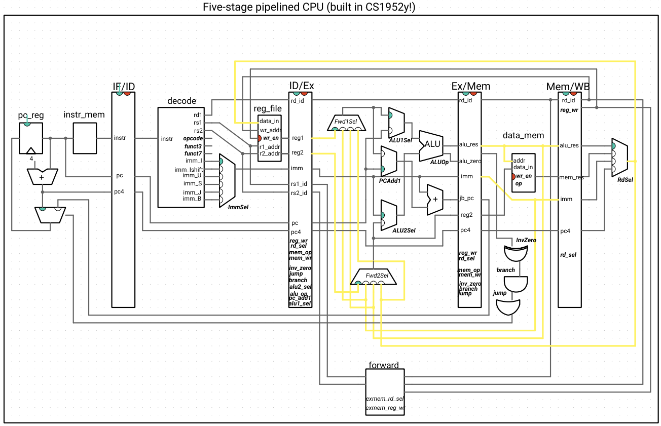
Here is our CPU, with the forwarding unit:
Note that the outputs of the forwarding unit are not indicated as wires and are the selection signals for the new muxes: Fwd1Sel and Fwd2Sel. The italicized names inside of the forwarding unit are the signals from the exmem register that we haven’t drawn the wires for. All other wires connected to the forwarding unit are inputs.
This may look like a distressing quantity of wires, so we highlight the wires that forward data to show that, alongside that logic, the new additions are the two multiplexers and the forwarding unit, with everything else staying the same:
If we try out our hazardous code examples, we see that they work correctly now.
Step 4: Resolving the last data hazard by stalling
There is one data dependency that cannot be solved using forwarding:
addi s0 x0 11
sw s0 0(sp) # resolved by forwarding
lw s1 0(sp) # s1 = 11; no dependency; memory updates immediately in mem stage
addi s2 s1 4 # s2 = 11 + 4 = 15; s1 dependency 1 instruction ago
This is because the lw instruction is in the Mem stage when the addi instruction is in the Ex stage, so the load result is not ready. But something strange happens when we run this code on our 5-stage processor with forwarding – can you explain what is going on, based on our forwarding logic?
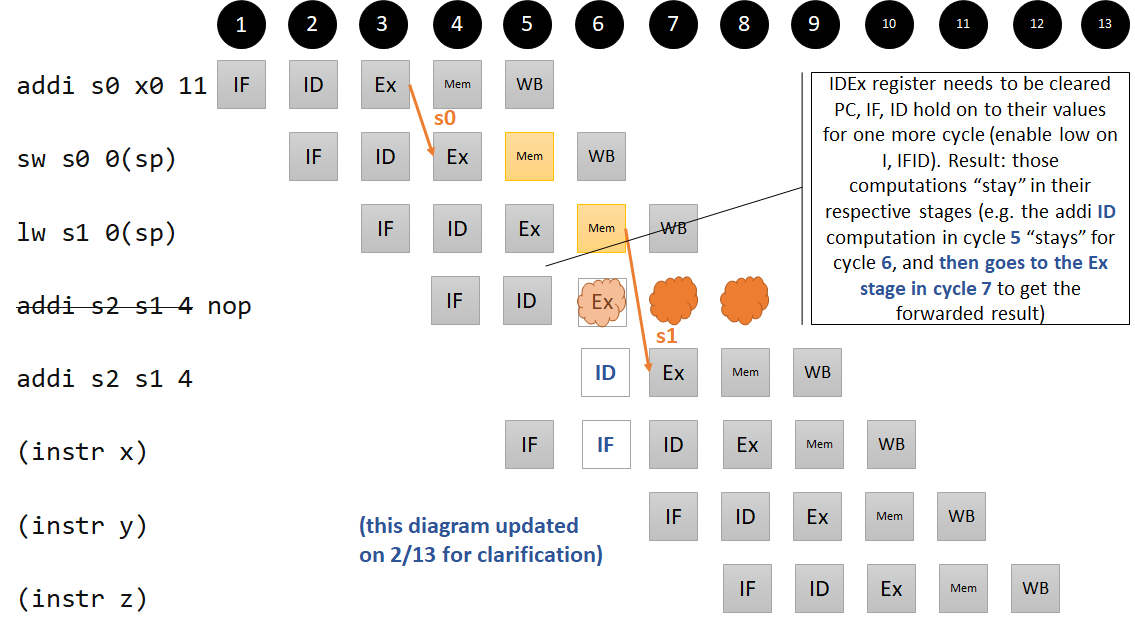
To run this sequence of instructions correctly, the CPU needs to insert a NOP between the load instruction and the add instruction if there is a dependency.
Pipeline diagram for our Mem/Ex hazard that requires stalling
A hazard unit in the ID stage is able to do this:
if (decode.rs[1/2]_id == idex.rd_id) and
  (decode.alu[1/2]_sel == reg) and
  (idex.rd_id != 0) and
  (idex.mem_op == [load operation]):
    stall
The (decode.alu[1/2]_sel == reg) condition checks to see that the source register in question is actually being used – since those bits are passed around regardless of the type of instruction, sometimes they may be part of an immediate field and still match rd, and we do not want to stall in that case. We did not need this clause in the forwarding unit, because the alu[1/2] selection multiplexers came after the forwarding multiplexers and took care of routing the correct data for us.
How do we implement the stall? Since the hazard unit is in the ID stage, we need to insert an instruction coming out of the ID stage that does nothing. Hence, we clear the ID/Ex pipeline register when we detect this hazard. We also can’t lose track of the instruction we are stalling, so we disable the IF/ID pipeline register and the PC register, so that they hold on to their values for one more clock cycle.
We also incorporate the flushing logic from step 2 into our hazard unit. Not only does this put all the pipeline stall/flush logic in one place, it allows us to handle a subtle but important interplay between data and control hazards. When a jump or branch happens, we shouldn’t drive the if_enable signal low, even if a data hazard is being detected in the ID stage, because the fetch stage will have the correct logic to fetch the instruction when the branch/jump reaches the mem stage.
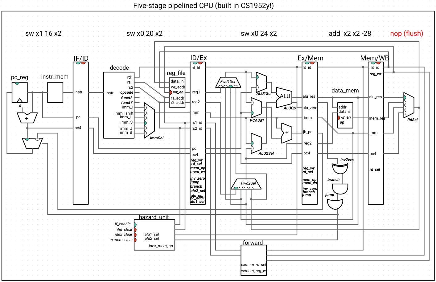
The inputs to the hazard unit are on the right, and the outputs (if_enable, which enables the PC register and IF/ID pipeline register; and idex_clear, which clears the ID/EX register) are signals on the left. Normal (non-hazard) operation is when if_enable is high (green) and idex_clear is low (red).
Now our CPU works correctly and performs fairly well! While this is the design discussed in P&H, we didn’t have to split up our computation into five stages – your homework will explore a design with four stages and with six stages.