Networking and communication
Last day for on-time checkoff: Tuesday, 11/14 (two weeks)
Prelab due 10/30/22 at 11:00 am
Writeup due 11/13/22 at 11:00 am
About
In this lab, you will explore different ways microcontrollers can interact with other entities, such as other microcontrollers and the internet. You will use the MKR1000’s built-in serial capabilities, and then write your own software UART to build understanding of how serial communication works. You will also see how to use your MKR1000s’ built-in WiFi modules to communicate with a webpage. By the end of this lab, you should be comfortable with using your Arduinos to communicate with other devices.
Lab 7 Rubric
Resources
Materials
Included in your kits:
- 2x Arduino MKR1000 and USB cable
- 5 resistors (3 x 1kΩ 2 x any size, both same size)
- 1 x RGB LED or 1 each of red, blue, and green LED
- Jumpers/wires
Provided:
- None necessary
Steps
-
If you haven’t registered your Arduino to the
Brown-Guestnetwork, installed the WiFi101 library, updated firmware, or uploaded thewww.random.orgSSL certificate as described in the prelab and this Ed post, do so now. Only one Arduino from each group needs to go through these steps. -
Your Arduino has built-in serial communication that you can use to send data between two Arduinos. Explore this here:
-
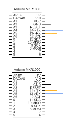
Wire up the following circuit. Notice that the TX pin of one Arduino goes into the RX pin of the other Arduino, and vice versa. Check that you haven’t mixed this up before powering on your circuit. Also, be sure to connect the GND pins of both Arduinos to each other! For this circuit, you do not have to put both Arduinos on the same breadboard, or any breadboard at all. If you want, you can wire up this circuit by using 3 stranded jumper wires and putting them directly into the pin headers of the Arduinos.
-
You can connect both Arduinos to one computer, or use two different computers. If you are using the same computer, you can switch between Arduinos by changing the port under
Tools -> Port. You will have to do this even if you have multiple IDE windows open. Notice also that the Serial monitor changes which Arduino it is receiving data from based on which port is selected – this sometimes even happens in both IDE windows. -
The Serial documentation shows that the TX and RX pins of the MKR1000 are associated with
Serial1.Hence, you can initialize the communication between Arduinos just like you initialized communication with the Serial monitor:void setup() { Serial.begin(9600); // Initialize serial monitor while (!Serial); // Wait for serial monitor to start (need this for USB serial) Serial1.begin(9600); // Initialize TX/RX communication (do not need to wait) } -
Make a new sketch called
sender.inothat, in theloop()function, uses Serial1.write to send a string of your choosing, such as “Hello World!”, every 2 seconds, via Serial1. Upload it to one of your Arduinos. -
Make a new sketch called
receiver.inothat, in theloop()function, reads bytes from Serial1 into a buffer and then prints that buffer to the Serial monitor (the computer screen). Refer to the Serial.read documentation to see how to do this (remember to useSerial1). You can castbytestocharsdirectly, i.e.Serial.println((char) b)ifbis of typebyte. It is okay to print each character on its own line. Upload it to your other Arduino and open the serial monitor. If you see the Serial monitor printing your string from 2d above, get checked off by a TA!
-
-
Now connect the sender to the internet!
-
Download the starter code and open
lab7.inoas a new Arduino project. Run the code on the sender Arduino and observe the output on the Serial monitor (you do not have to be running the receiver Arduino for this step). What do you see? -
Study the code in
lab7_wifi.ino. InsendHTTPReq, the code uses the random.org http API to ask for a random number between 1 and 3 (inclusive). Typically, random.org uses atmospheric noise to generate random data, but you can also provide a seed so that it uses its pseudorandom number generation algorithm. Every time you make a request with the same seed, you will get the same result – this will be useful for us when we want all of the Arduinos in the class to be in sync! For now, our code usesmillis()as the seed.In
readWebpage, the code outputs the response from random.org. As given to you, the code prints the entirety of this response, including header information. Change the code so that onlyRED(for a response of1),GREEN(for2), orBLUE(for3) gets printed to the Serial monitor whenever the file is fetched. You can ignore any server errors or responses that don’t have1,2, or3. Hint: a successful HTTP response will have the message we’re looking for in the second-to-last character. How can you modify thewhile (client.available())loop to keep track of the second-to-last character that was seen? -
Modify your sender code such that it sends one of ‘r’, ‘g’, or ‘b’ (depending on what it gets from random.org) gets sent to the receiver via Serial1 (remember to add
Serial1.begin(9600)insetup). The end result is that the receiver should not be connected to the internet, but should be displaying the color corresponding to the HTTP request in (more or less) real-time because it is communicating with the sender (which is connected to the internet). Observe that the receiver is receiving and displaying these values (you should not have to change your receiver code). Get checked off by a TA.
-
-
Now write your own Serial transmitter and receiver! As stated in the prelab, you will implement UART in software.
-
Comment out the
Serial1code from step 3c. Also uncomment the lines inlab7.inoafter the comment that saysUncomment for LAB STEP 4a.Observe howuartReceiveis an interrupt service routine that triggers wheninPinis FALLING (goes from HIGH to LOW). Check with your partner that you agree on why this is. -
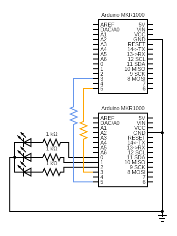
Wire up the following circuit. For the LEDs, you may use one RGB LED or a red, a green, and a blue LED. Just make sure that red is connected to pin 0, green to 1, and blue to 2 (make a new sketch to test this if you’re using the RGB LED). The resistors between pins 3 and 5 of both Arduinos can be any resistance (technically they are not necessary if the pins are configured correctly, but we add them to limit the current just in case of a mistake in software).
-
You will upload the same code to both Arduinos, except for the line under
LAB STEP 4c/4g, which will configure one as the sender and one as the receiver. This means that both Arduinos are capable of sending and receiving data, even though, in this lab, the sender will be using the send function only and the receiver will be using the receiver function only. The writeup asks you more about this design. -
The sender and receiver have the following roles in this step:
Sender: continuously reads 1, 2, or 3 from random.org using the seed described below and stores data in a buffer (
sBuf). Reads from the buffer and sends ‘r’, ‘g’, or ‘b’ to the receiver via the UART.Receiver: reads ‘r’, ‘g’, or ‘b’ from the UART into a buffer (
rBuf). Reads from the buffer and lights up the corresponding LED.sBufandrBufand the corresponding indices are defined inlab7.h. Characters are stored in 8 bits, so you can cast acharto abyte(and vice versa) easily (e.g.(byte) 'r'). -
Code up the necessary code for the sender. We have commented
LAB STEP 4ein some places of the code to guide you. In the functionuartSend(lab7_uart.inofile), you should fill in the blanks according to the answers from your prelab. Notice how the clock period of the UART is enforced using software.You should make functions that read from/write to the buffer
sBufatomic, by disabling interrupts whenever you write to/read from the buffer. The Arduino functions interrupts() and noInterrupts() will help you accomplish this. Also remember to check thatsBufwill not fill up before adding to it!We want all of the devices in the room (including the TA reference circuit) to have the LEDs changing in the same sequence, give or take a second or two. We can accomplish this by all using the same seed at the same time. For now, we’ve been using
millis()as our seed in our HTTP request to random.org. However,millis()gives us the time since the power-on of our specific Arduino.In order to all have the same seed at the same time, we will use (the number of seconds since Jan 1, 1900) / 3 (rounded down using integer division) as our random seed, so that a new random value is received every 3 seconds. In order to get the time, we communicate with an NTP server (in class, we learned that NTP is a protocol that uses very precise time servers). We give you the code to do this in
lab7_wifi.ino. The code borrows heavily from theWifiUdpNtpClientexample found underExamples -> WiFi101. UDP is an internet protocol that is sometimes faster than TCP (used by HTTP requests), since it makes no guarantees about packets being received in order or at all. This is fine for a reliable time server for which we know the IP address. (More information about the difference between UDP, TCP, and other internet protocols is outside the scope of 1600 and can be learned in a networking class).You don’t have to make multiple requests to the NTP server – the one the starter code makes at the beginning of the code is sufficient to keep track of time for our purposes. Take a look at how we use
millisand some values we stored to compute the current number of seconds since Jan 1, 1900 in theconnectToNTPfunction, and adapt this idea to change the random.org HTTP request seed to (the number of seconds since Jan 1, 1900) / 3. -
Code up the receiver. We have commented
LAB STEP 4fin some places of the code to guide you. When you check the parity bit for messages you receive, you should discard messages for which the computed parity does not match. You should also discard messages that are not ‘r’, ‘g’, or ‘b’. Similarly to the step 4e, you should fill in the blanks touartReceiveaccording to the prelab, make functions that read from/write to the bufferrBufatomic, and remember to check thatrBufwill not fill up before adding to it! -
Upload the code to both Arduinos, remembering to toggle the SENDER flag (under comment
LAB STEP 4c/4g). Run and debug the code. When debugging, it may be helpful for the receiver to write what it is receiving (and the messages it may be discarding) to the Serial monitor. Once you are confident it works, get it checked off by a TA. Your TA will have a reference implementation that reads from the same website, so you should be seeing your LEDs and the TA’s LEDs display the same light sequence (give or take a second, and assuming the network is reliable).
-
-
Turn in the
lab7_uart.inocode on the Lab 7: Code Gradescope assignment