Embedded Programming and Memory
Prelab due 9/26/22 at 11:00 am
Writeup due 10/03/22 at 11:00 am
About
In this lab, you will interact directly with the registers for the AMD chip that operates your Arduino. While in previous labs you saw how to use the Arduino API to control input and output on pins, most MCUs do not come with such a useful layer of abstraction. In this lab, you will learn what happens under the hood of this abstraction, by setting bits in MCU control registers yourself. In doing this, you will gain some experience interpreting a datasheet for a device as complex as a microcontroller. In the last part of the lab, you will also get some sense of the memory limits of this microcontoller.
Lab 3 Rubric
Resources
- Arduino API
- Arduino Help
- Our datsheet guide
- MKR1000 schematic
- SAM D21E/SAM D21G/SAM D21J Datasheet Summary
- Atmel SAM D21 Family Datasheet DATA/STORAGE WARNING: 1115 page PDF
- SAM D21 peripheral header files
Materials
Included in your kits:
- Arduino MKR1000 and USB cable
- Breadboard
- 1 LED (any color)
- 2 push buttons
- 3 resistors (1 x 1kΩ; 2 x 10kΩ)
- Jumpers/wires
Provided:
- None necessary
Steps
-
With your partner, come up with a high-level, 3-5 sentence summary of how Arduino code gets compiled to code that is compatible with the architecture of the microcontroller on the Arduino. Tell this summary to a TA. If you are waiting for a TA, go ahead and get started on the next steps of the lab.
-
Wire up the following circuit. At different steps in the lab, we will work with different parts of the circuit.
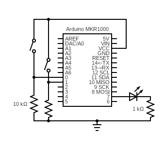
Test that each component is working by writing some code to turn on the external LED and the on-board LED (on pin 6) and output the signal of each button onto the serial monitor, similar to Lab 1. You can just poll
digitalRead(...)for the buttons, instead of setting up an interrupt handler. If you need help debugging your lab, your TAs will first ask you to pull up this code to make sure your circuit is working before going on to more complicated diagnosis. -
Create a new sketch. In this sketch, you will work with the PORT registers to blink the onboard LED.
-
Refer back to Question 4 of the prelab, where you determined the register bits to set and clear to drive Pin 6 as an output.
-
To read and write to the port registers in Arduino code, you can access them using
PORT->Group[PORTX].REGNAME.reg, whereXisAorB(the port you are referencing), andREGNAMEis the name of the register, likeDIR. -
Write some Arduino code to use the registers to change the mode of Pin 6 to output (in the
setup()function of a blank Arduino sketch), and drive it high (on) for 1 second and drive it low (off) for two seconds (in theloop()function). You may usedelay(...)in your code, but notpinMode(...)ordigitalWrite(...). It may be helpful to look back at the review of bit operations in Question 2 of the prelab.
For this step, you can either use the read-modify-write version of the registers, or use the
SET/CLRregisters (refer to our how to read a datasheet guide for more details). We recommend trying both!- Upload, run, and debug your code, and, when working, get it checked off by a TA.
-
-
Now, you will modify the code to read the input from one of the buttons and use it to drive the LED on when the button is pressed down and off when the button is not pressed.
-
Referencing the prelab see what register bits to set or clear, set the mode of Pin 0 to input, and read its input value (you will have to refer to the
PORTregisters in the datasheet to see how to read this value). Write some code to control the on-board LED with the button. When the button is held down, the LED should be lit. When the button is released, the LED should not be lit. Again, you may not usepinMode(...),digitalWrite(...),digitalRead(...), orattachInterrupt(...)in your code. -
Upload, run, and debug your code, and, when working, get it checked off by a TA.
-
Save the code as
registers1.inoto be submitted later.
-
-
Create a new sketch. In this sketch, you will set up an interrupt on Pin 0 to detect the rising edge of the signal, indicating that the button has been pressed.
-
In
setup(), Configure Pin 0 as an input as above. Also configure the pin to be used by the External Interrupt Controller (EIC) based on your answers in prelab Question 5. (The registers you will set in this step are thePINCFGandPMUXregisters you identified in that question).The SAM D21
port.hheader file file gives some convenient definitions of the bits. For example, instead of manually writing bit 2 to PINCFG to enable the pull resistor, you can use the pre-defined macroPORT_PINCFG_PULLENwithout needing to shift the bits, so you can connect all the relevant flags with a bitwise-or:PORT->Group[PORTX].PINCFG[y].reg = PORT_PINCFG_PULLEN | ...As you saw in the prelab, you will reference the relevant PMUX register using
PORT->Group[PORTX].PMUX[y/2].reg -
Still working in
setup(), initializeSeriallike in labs 1 and 2, and useSerial.println(...)to print the PM and NMI registers from question 6 of the prelab to the serial monitor in binary, so that you can verify that the necessary bits (identified in prelab Question 6.1) are already set. PM registers can be accessed usingPM->REGNAME.reg, and similarly with NMI. -
In
setup(), configure the GCLK according to the bits you determined in Question 6.2 of the prelab. The registers you will be writing to areGENCTRLandCLKCTRL. Macros that name the bits for these registers (for example,GCLK_GENCTRL_IDCare found ingclk.hin the header files.15.6.6 of the datasheet tells us that when we write to GENCTRL, we need to also wait for the SYNNCBUSY bit of the STATUS register to clear before proceeding, which we can do by adding the following line after writing to GENCTRL:
while(GCLK->STATUS.bit.SYNCBUSY);As described in our datasheet guide, be sure not to use
|=to write toGENCTRL, because it may cause an incorrect ID configuration inGENCTRLand causeSYNCBUSYto hang indefinitely. -
Now that we have configured the generic clock, it is time to configure the EIC, using your answers from prelab Question 7 (there are three registers to write to for this step). You can refer to
eic.hin the header files for the bit macros. You can reference the registers usingEIC->REGNAME.reg. -
Finally, enable the EIC using the CTRL (21.8.1) register. Because CTRL is write-synchronized, we also need to wait for the
EIC->STATUS.bit.SYNCBUSYbit to clear, as for theGCLK STATUS SYNCBUSYbit above. -
Enable interrupts on individual pins by writing a 1 to the appropriate index bit of the
INTENSETregister (21.6.6/21.8.7). -
The nested vector interrupt controller (NVIC) manages all the interrupts on the board. We set the priority of the EIC at 3 because the button push isn’t timing-critical, and we also enable the interrupt request definition (IRQ, the function that handles the interrupt) using the following two lines:
NVIC_SetPriority(EIC_IRQn, 3); NVIC_EnableIRQ(EIC_IRQn); -
Finally, implement the function
void EIC_Handler(void)with the desired behavior. For this code, you should increment the number of times the button has been pushed, and print the number to the serial monitor every time the button is pushed. You must write a 1 to the appropriate index bit of the EIC INTFLAG register to clear the interupt at the end of the handler function (21.8.8).
-
Upload, run, and debug your code. If it is not working, carefully read through every substep of this lab step, to see if you missed configuring any registers. Once you are confident your code works demo it to a TA.
-
-
In this step, you will enable interrupts on the other button (pin 1). Remember to check which Port/pin Arduino pin 1 is on, and which EIC index corresponds to that port pin. You will then change the EIC_Handler function such that the external LED toggles between on and off whenever the pin 1 button is pressed, and the on-board LED toggles between on and off whenever the pin 0 button is pressed:
-
You should configure both LEDs as outputs, just like you did for the on-board LED in Step 3.
-
You should configure pin 1 the same was you did pin 0, by writing the corresponding registers. Note that the EIC handles all external interrupts on all pins, so your GCLK configuration shouldn’t change. You will, however, need to enable some extra bits on the three EIC configuration registers.
-
When an interrupt is triggered and the
EIC_Handlerfunction is called, you can check which EIC index is responsible for the interrupt by reading theINTFLAGregister and seeing which bit is a 1. After handling the interrupt, you then write a 1 to that bit again to clear the interrupt. This may not seem intuitive, but that is why this register is called the Interrupt Flag Status and Clear register (see 21.6.3).How would you check if a bit at a certain index of a register is set? Refer back to pre-lab Question 2 and discuss with your partner.
Implement this check to determine which button was pushed, and toggle the external LED when the pin 1 button is pressed and the on-board LED when the pin 0 button is pressed. Don’t worry about handling the case where both buttons are pressed at the same time.
-
Finish writing your code, and upload, run, and debug it. When it is working, check it off with your TA.
-
Save the code as
registers2.inoto be submitted later.
-
-
You can do this last step during lab with your partner, or alone after the lab. This step requires your Arduino but doesn’t require you to build any circuits.
-
Create a new sketch that declares and initializes two global variables (of types(s) of your choosing), three local variables in the
setup()function, and an emptyhelper()function. InitializeSerialinsetup()and use it to print something inloop()(you can makeloop()print once by adding awhile(true);at the end ofloop()). -
Using
Serial.println(...)in thesetup()function, print out the memory addresses of: both global variables, all three local variables, theloop()function, and thesetup()function, and one of the registers you used in this lab in hexadecimal. You can access the address of a variable, function, or register by preceding it with&:&varnameor&loopor&(PERIPHERAL->REGNAME.reg)(don’t put the parentheses after the function name, because you are not calling the function). You can print something in hex using the syntax belowSerial.println((unsigned int) thing_to_print, HEX). It will be helpful to precede each address with a helpful label, e.g.Serial.print("A local variable: "); Serial.println((unsigned int) &local_var, HEX); -
Now declare two global variables of type
int*:addrandaddr_static. In thehelper()function, declare and initialize a local variable of typeint. Write down the value you initialized this variable to. Inhelper(), store the address of this variable intoaddr(to get the address of a variable, precede it with&, i.e.addr = &var). Also create a local static variable inhelper(), and store its address inaddr_static. Back in thesetup()function, callhelper()and then dereferenceaddrandaddr_staticto print the values stored at their addresses (to dereference, use*, e.g.Serial.println(*addr)). Also print the values ofaddrandstatic_addr(since they’re pointers that store addresses, you can just print them using e.g.Serial.println((unsigned int) addr)). -
Make sure both partners have a copy of the output to refer to in the lab writeup.
-
At the very end of the
setup()function, include the following code:int* corrupt_loop = (int*) &loop; *corrupt_loop = 32580; // can use any nonsense valueRun the code. What do you notice (hint: what is missing that existed in the previous output?) You will be asked to explain this in the writeup.
Note: after doing this, try to upload a new sketch, like BareMinimum, to the board. The IDE should hang. You can reset the bootloader of the Arduino by double-pressing the reset button, which should allow you to upload the sketch (check to see if the port that the Arduino is on has changed when you reset the bootloader).
-
-
Turn in your work:
-
Save your code from steps 4c and 6e. Upload this to the “Lab 3 Code” assignment on Gradescope (include all partner(s) on the submission).
-
INDIVIDUALLY, complete the Lab 3 writeup assignment on Gradescope.
-