Runtime monitoring
Table of contents
- About
- Prelab (due date: November 9, 2021 at 4pm)
- Procedure (you have until November 23 to check off and turn in this lab)
- Writeup
About
In this lab, you will be given compiled binaries of “air conditioner” software to run on one of your Arduinos. You will be given a reference working binary, and a buggy binary. Your job will be to use the second Arduino to monitor what is happening on the first Arduino (the air conditioner) and use computations on the monitored values to report if/when a safety violation occurs. The runtime monitor will listen to messages sent by the air conditioner and also observe some of the electrical signals being sent to/from the air conditioner. Every time it receives a message, it will check each of the 10 safety properties described in the lab. By the end of this lab, you should understand how a runtime monitor can tap into the interfaces of a running system in order to ensure that it is operating safely.
Lab 8 Rubric
Resources
Materials
Included in your kits:
- 2x Arduino MKR1000 and USB cable
- 5 resistors (4 x 560Ω - 1kΩ, 1 x 220 Ω)
- 3 x blue LED
- 1 x yellow LED
- 1 x potentiometer
- 1 x button
- Jumpers/wires
Provided:
- None necessary
Prelab (due date: November 9, 2021 at 4pm)
Duplicate the following worksheet and fill it out digitally, or print it, fill it out on paper, and scan it to turn it in. The idea is to be able to refer to this worksheet during the lab.
Procedure (you have until November 23 to check off and turn in this lab)
-
As described in the prelab, you will be working with two Arduinos, one that is meant to emulate an air conditioner and one that is meant to monitor the air conditioner. You will be given a working executable to load on your AC Arduino that you will monitor (and observe that there are no safety violations). You will then be given a mystery binary, which is meant to represent an AC that has shipped with faulty software or sensors, and you will use your monitor to figure out which bug the AC has.
-
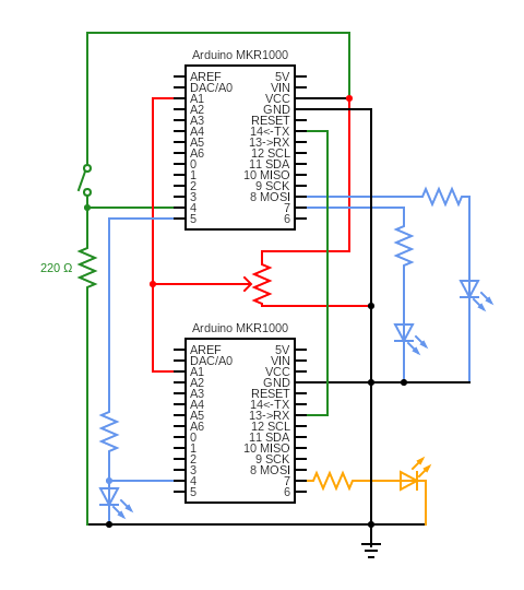
Wire up the following circuit. The top Arduino is the AC Arduino, and the bottom Arduino is the runtime monitor. We used blue LEDs for the three LEDs connected to the AC and a yellow LED for the LED connected to pin 7 of the monitor. The resistors in series with the LEDs can be anywhere from 560Ω to 1kΩ. If you are using two breadboards for the circuit, we suggest wiring the three blue LEDs, the button, and the potentiometer on the same board as the AC Arduino, and using the long stranded jumpers to make the necessary connections to the monitor Arduino.
-
Load the working binary onto the Arduino by following these instructions:
-
Connect the AC Arduino to the computer using the USB cable. Open the Arduino IDE and open the Blink built-in example.
-
Under
File -> Preferences(Arduino -> Preferenceson Mac), check the “Show verbose output during: upload” box. Be sure to press OK at the bottom to save your preferences.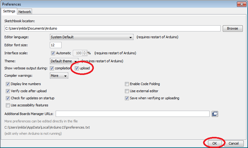
-
Press the upload button. Once the code is uploaded, scroll up in the IDE terminal to find and copy the upload command up to and including the
-i -e -w -vflags, which will look something like this (click image to enlarge if needed):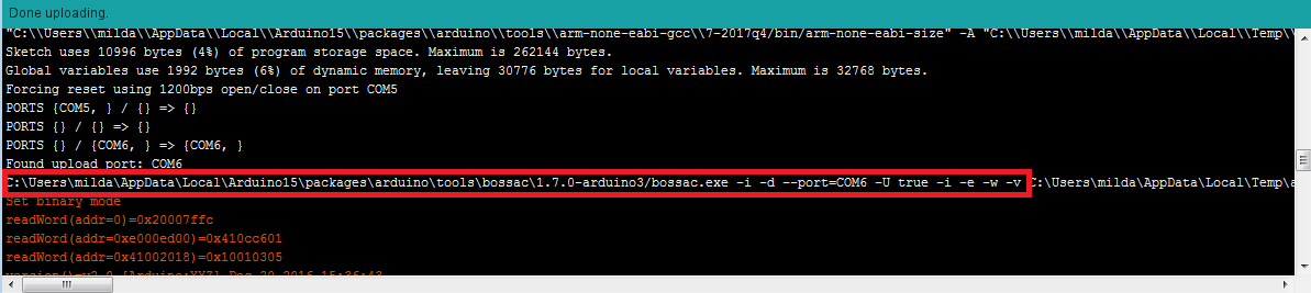
-
Exit the IDE. Download the starter binary and make a note of the full filepath of its location. Open your terminal (Linux/Mac) or command prompt (Windows) and paste the upload command, followed by the full filepath of the starter binary location, followed by
-R, but do not run the command yet. For example, on Windows, your command might look like:C:\Users\name\AppData\Local\Arduino15\packages\arduino\tools\bossac\1.7.0-arduino3/bossac.exe -i -d --port=COM6 -U true -i -e -w -v C:\Users\name\Downloads\ac_binary.ino.mkr1000.bin -R -
Double-press the RST button on your AC Arduino quickly, so that it enters bootloader mode. The LED on your board will fade in and out. Now run the command above so that the binary is uploaded onto the Arduino.
-
Observe the AC system working. In particular, verify that pressing the button on and off turns the system on and off. Also observe that one of the LEDs (connected to pin 8 of the AC Arduino) indicates the desired temperature and should change brightness when you turn the potentiometer. One of the other LEDs (connected to pin 7 of the AC Arduino) indicates the current temperature and should eventually increase in brightness if the AC is off and decrease in brightness if the AC is on. Finally, the last LED (connected to pin 5 of the AC Arduino) should either be on or off at any given time and indicate whether the AC is on or off.
-
-
Implement your monitor: note for this and the subsequent step: this is the last structured lab session, and the due date for this lab is extended, so if implementation or debugging are taking longer than expected, keep in mind that you have the option of also working on this lab with TA support next week and the week following.
-
Download, extract, and open the monitor starter code.
-
The only file you will need to change (initialize/update variables and check properties) is
monitor_functions.ino. Observe that two properties (properties 2 and 4) have been implemented for you, 2 inMONITOR()and 4 inmonitor_system_on(). Pay attention to howtime_of_last_sys_changeandprevious_sysare updated after the property is checked. Also notice thestop_systemfunction that is called when a property is violated. This function turns off the yellow indicator LED (this serves as a visual cue on the board that the system would be stopped if this were a real device – the monitor in this lab does not actually turn the system off for convenience of debugging), stops the monitor, and prints the given error message. When you upload and run this monitor code on the monitor Arduino, you should not get any violations. -
Implement the rest of the safety properties 1, 3, and 5-10, based on your prelab answers. Run the monitor code on the monitor Arduino and play with the AC interfaces (button and potentiometer). Be sure that the potentiometer is firmly seated in the breadboard and that you are not turning it past its limits, to avoid false positives of violations. Hint: instead of re-uploading the monitor code if this happens, you can simply press the reset button on the monitor Arduino and wait a few seconds for the monitor to restart. When running the provided binary and your monitor, no property violation should occur because the code should be working as intended. Once you are confident that your monitor is correctly monitoring the system, get it checked off by a TA. While waiting for a TA, read the next step.
-
Your TA will ask you to change the check for one of the properties 1, 3, or 6 (your TA will tell you which one) so that it is violated with some input, and show the violation. For example, to trigger a violation for property 2, you could change the check from 750ms to 2000ms and then press the on/off button twice (more than 1 second but less than 2 seconds apart) to trigger the violation. The idea is to show that you understand what each of the properties means, how the system is working, and what is necessary for a violation to happen. Once you do this, get checked off by a TA.
-
-
Solve the mystery!
-
Download and extract the buggy binaries. The buggy binaries each violate one of the properties 1-10 at some semi-random point in the code (that is, the violation may not show up immediately). For example, upload the
bug_prop4.ino.mkr1000.binbinary to the AC and observe that, after a few seconds or so, the monitor shows that property 4 was violated. -
Upload the buggy binary that your TA assigned to you onto the AC Arduino, and run your monitor Arduino. Play with the AC interfaces (button and potentiometer) to solve the mystery of which property the buggy binary violates. Get checked off by a TA, and take note of the buggy binary (letter) and violated property (number) for the writeup. If it is taking you longer than 15 minutes to find the property violation, ask your TA for a hint and review your monitor code. If it takes you longer than 20 minutes after receiving the hint, ask your TA to assign you a different buggy binary.
-
Writeup
In a document, answer the following questions. Make sure the report states your name (first and last) and your partner’s name (first and last)! (if you worked alone, write “no partner”)
1. Think through the following list of concepts you encountered in the lab, and note if you have questions about any of them. Please also include any questions about concepts not listed here. If you have no questions, just write “no questions”
runtime monitoring, observing electrical signals, monitor variable initialization, computing properties
2. What, if any, frustrations did you encounter while doing the lab?
3. What was your main takeaway from this lab?
4. The monitor monitored some of the electrical signals sent by/to the AC (the potentiometer, the AC LED) but not others (the button, the temperature LEDs). In the real world, it would be beneficial for a monitor to monitor all relevant signals; however, the particular signals we left out had some particular properties that made them hard to monitor without introducing a lot of complexity. What causes this complexity? Hint: for the button, think back to lab 1 and any strange button behavior you observed, and speculate on how this could cause a discrepancy in what the monitor observes from the signal vs what the AC observes. Similarly, for the temperature LEDs, think back to lab 2 and what you learned about PWM.
5. Which buggy binary were you asked to use in step 5b? Which property did it violate? Speculate on what might cause the bug (if it could be a hardware failure, name the sensor or actuator that would fail. If it could be a software failure, speculate on what the bug might look like in code). We are not looking for one “right answer” here, but rather that you can do a very high-level form of FMEA or FTA.
6. Including the pre-lab and writing this document, how long did this lab take you? You will not be judged on your answer for this question, the numbers are just being used for calibration purposes for later labs and future course offerings.
Turn in the code (the monitor_functions.ino file) and the document (saved as a PDF; separate from the code) on Canvas.