Networking and communication
Table of contents
About
In this lab, you will explore different ways microcontrollers can interact with other entities, such as other microcontrollers and the internet. You will use the MKR1000’s built-in serial capabilities, and then write your own software UART to build understanding of how serial communication works. You will also see how to use your MKR1000s’ built-in WiFi modules to communicate with a webpage. By the end of this lab, you should be comfortable with using your Arduinos to communicate with other devices.
Lab 7 Rubric
Resources
Materials
Included in your kits:
- 2x Arduino MKR1000 and USB cable
- 5 resistors (3 x 1kΩ 2 x any size, both same size)
- 1 x RGB LED or 1 each of red, blue, and green LED
- Jumpers/wires
Provided:
- None necessary
Prelab (due date: October 26, 2021 at 4pm)
Duplicate the following worksheet and fill it out digitally, or print it, fill it out on paper, and scan it to turn it in. The idea is to be able to refer to this worksheet during the lab.
Procedure
-
If you haven’t registered your Arduino to the
Brown-Guestnetwork, installed the WiFi101 library, or updated firmware as described in the prelab, do so now. Only one Arduino from each group needs to be registered. -
Your Arduino has built-in serial communication that you can use to send data between two Arduinos. Explore this here:
-
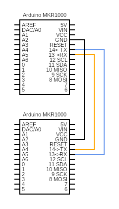
Wire up the following circuit. Notice that the TX pin of one Arduino goes into the RX pin of the other Arduino, and vice versa. Also, be sure to connect the GND pins of both Arduinos! For this circuit, you do not have to put both Arduinos on the same breadboard, or any breadboard at all. If you want, you can wire up this circuit by using 3 stranded jumper wires and putting them directly into the pin headers of the Arduinos.
-
You can connect both Arduinos to one computer, or use two different computers. If you are using the same computer, you can switch between Arduinos by changing the port under
Tools -> Port. You will have to do this even if you have multiple IDE windows open. Notice also that the Serial monitor changes which Arduino it is receiving data from based on which port is selected. -
The Serial documentation shows that the TX and RX pins of the MKR1000 are associated with
Serial1.Hence, you can initialize the communication between Arduinos just like you initialized communication with the Serial monitor:void setup() { Serial.begin(9600); // Initialize serial monitor while (!Serial); // Wait for serial monitor to start (need this for USB serial) Serial1.begin(9600); // Initialize TX/RX communication (do not need to wait) } -
Make a new sketch called
sender.inothat, in theloop()function, uses Serial.write to send a string of your choosing, such as “Hello World!”, every 2 seconds, via Serial1. Upload it to one of your Arduinos. -
Make a new sketch called
receiver.inothat, in theloop()function, reads bytes from Serial1 into a buffer and then prints that buffer to the Serial monitor. Refer to the Serial.read documentation to see how to do this. You can castbytestocharsdirectly, i.e.Serial.println((char) b)ifbis of typebyte. It is okay to print the characters line by line. Upload it to your other Arduino and open the serial monitor. If you see the Serial monitor printing your string from 2d above, get checked off by a TA!
-
-
Now connect the sender to the internet!
-
Download, extract, and open the starter code as a new Arduino project. Run the code and observe the output on the Serial monitor (you do not have to be running the receiver Arduino for this step). What do you see?
-
Study the code in
lab7_wifi.ino. Notice that the code fetches and reads in lab7LED.txt, which is set to change to a random value from{RED, GREEN, BLUE}every 0.5-2.5 seconds. As given to you, the code prints the entirety of what it sees when requesting this file from the server, including header information. Change the code so that onlyRED,GREEN, orBLUEgets printed to the Serial monitor whenever the file is fetched. You can ignore any server errors that are returned (which happen when you try to fetch while the website script is writing a new value to the file). -
Modify your sender code such that it sends one of ‘R’, ‘G’, or ‘B’ (depending on what it reads from the file on the website) at approximately 250ms intervals to the receiver via Serial1. Observe that the receiver is receiving these values (you should not have to change your receiver code). Get checked off by a TA.
-
-
Now write your own Serial transmitter and receiver! As stated in the prelab, you will implement UART in software.
-
Remove the
Serial1.begin(9600)line inlab7.ino(after the comment readingREMOVE THE FOLLWOING LINE AFTER COMPLETING STEP 3 OF LAB). Also uncomment the lines after the comment readingUncomment for LAB STEP 4a.Observe howuart_receiveis an interrupt service routine that triggers whenin_pinis FALLING (goes from HIGH to LOW). Check with your partner that you agree on why this is. -
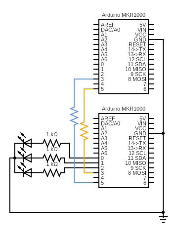
Wire up the following circuit. For the LEDs, you may use one RGB LED or a red, a green, and a blue LED. The resistors between pins 3 and 5 of both Arduinos can be any resistance (technically they are not necessary if the pins are configured correctly, but we add them to limit the current just in case of a mistake in software).
-
You will upload the same code to both Arduinos, except for the line under
LAB STEP 4c/4g, which will configure one as the sender and one as the receiver. This means that both Arduinos are capable of sending and receiving data, even though, in this lab, the sender will be using the send function only and the receiver will be using the receiver function only. The writeup asks you more about this design. -
The sender and receiver have the following roles in this step:
Sender: reads RED, GREEN, or BLUE from the website at approximately 250ms intervals and stores data in a buffer. Reads from the buffer and sends ‘r’, ‘g’, or ‘b’ to the receiver via the UART.
Receiver: reads ‘r’, ‘g’, or ‘b’ from the UART into a buffer. Reads from the buffer and lights up the corresponding LED.
Remember that characters are stored in 8 bits, so you can cast a character to a byte easily (e.g.
(byte) 'r'). -
Code up the sender. We have commented
LAB STEP 4ein some places of the code to guide you. In the functionuart_send(lab7_uart.inofile), you should fill in the blanks according to the answers from your prelab. Notice how the clock period of the UART is enforced using software.Remember from the prelab that you should make functions that read from/write to the buffer
s_bufatomic. The Arduino functions interrups() and noInterrupts() will help you accomplish this. Also remember to check thats_bufwill not fill up before adding to it! -
Code up the receiver. We have commented
LAB STEP 4fin some places of the code to guide you. When you check the parity bit for messages you receive, you should discard messages for which the computed parity does not match. You should also discard messages that are not ‘r’, ‘g’, or ‘b’. Similarly to the step 4e, you should fill in the blanks touart_receiveaccording to the prelab, make functions that read from/write to the bufferr_bufatomic, and remember to check thatr_bufwill not fill up before adding to it! -
Upload the code to both Arduinos, remembering to toggle the SENDER flag (under comment
LAB STEP 4c/4g). Run and debug the code. When debugging, it may be helpful for the receiver to write what it is receiving (and the messages it may be discarding) to the Serial monitor. Once you are confident it works, get it checked off by a TA. Your TA will have a reference implementation that reads from the same website, so you should be seeing your LEDs and the TA’s LEDs display the same light sequence.
-
Writeup
In a document, answer the following questions. Make sure the report states your name (first and last) and your partner’s name (first and last)! (if you worked alone, write “no partner”)
1. Think through the following list of concepts you encountered in the lab, and note if you have questions about any of them. Please also include any questions about concepts not listed here. If you have no questions, just write “no questions”
Serial, WiFi, UART, circular buffers, parity, atomic operations
2. What, if any, frustrations did you encounter while doing the lab?
3. What was your main takeaway from this lab?
4. Why is uart_receive an interrupt service routine that is triggered by in_pin going from HIGH to LOW? (1-2 sentences is fine).
5. We manually inserted delays in the uart_send and uart_receive functions to run the UART at a specific clock period.
a. What drawback do you see to this method?
b. What alternative would you propose? Would you still be able to use the Arduino API’s disableInterrupts() function for atomicity? Why or why not?
6. We wired up the circuit symetrically, so that both Arduinos are technically capable of sending and receiving UART messages from the code. Suppose one or both of your Arduinos was tasked with doing more complex computations such that it wasn’t always available to send or receive data. Drawing upon what you learned about protocols in class, how would taking advantage of the send/receive capability of both Arduinos to implement your communication to be more robust (less likely to miss messages)?
7. Including the pre-lab and writing this document, how long did this lab take you? You will not be judged on your answer for this question, the numbers are just being used for calibration purposes for later labs and future course offerings.
Turn in the code (your modifications to lab7.ino, lab7_wifi.ino, and lab7_uart.ino zipped together. There is no need to turn in the sender and receiver from step 2) and the document (saved as a PDF; separate from the zip of the code) on Canvas.