Embedded Design and Engineering
Table of contents
About
In this lab, you will translate requirements for a game into a Finite State Machine (FSM) description of the game implementation. You will then implement the FSM to run on your Arduino, to produce a game that is played with a physical gamepad and displayed on an LCD screen. By the end of this lab, you will have used a traceability matrix to map behavioral requirements to FSM transitions guards and behaviors and have practiced creating both FSM transition descriptions and code to match an FSM.
Lab 5 Rubric
Resources
- Arduino API
- Arduino Help
- LCD datasheet (you will likely not need to use this datasheet for the lab, but it is provided here for your reference)
Materials
Included in your kits:
- Arduino MKR1000 and USB cable
- 2 small or 1 large breadboard
- 1 16x2 LCD screen
- 1 Potentiometer
- 4 1MΩ resistors
- 1 220Ω resistor
- Jumpers/wires
Provided:
- Materials for gamepad
Prelab (due date: October 12, 2021 at 4pm)
Duplicate the following worksheet and fill it out digitally, or print it, fill it out on paper, and scan it to turn it in. The idea is to be able to refer to this worksheet during the lab.
Procedure
-
Construct a capacitive-touch game controller out of tape, cardboard, and foil. While you are waiting for materials to come around to you for this step, work on Step 2 (wiring up the circuit).

-
Obtain the following materials: four pieces of wire, about 6” (15cm) long, ends stripped; four squares of aluminum foil, measuring about 0.5” (1cm) per side; one square of packing tape; one square of cardboard the same size or slightly larger than the tape. (Optional) also obtain a piece of tape (length slightly greater than the diagonal of your cardboard square) cut in half lengthwise, for step e, and a short piece of tape, for step f.
-
Place the square of tape sticky-side up. Stick one end of each wire to the center of each edge of the tape, such that the exposed metal is entirely within the square.
-
Stick a square of foil over each wire end on the tape. Take care that none of the squares of foil touch each other.
-
Stick the piece of tape onto the cardboard square, such that the wire ends and foil are sandwiched between the tape and cardboard.
-
(Optional) secure the controller with more tape and use a permanent marker to indicate where the foil squares are. Here, we used one long strip of tape cut in half lengthwise, and placed each piece diagonally across the square to make an “x,” folding the tape over the edges of the cardboard. We also colored in one of the foil indicators, so that we can orient the square.
-
(Optional) roll up a piece of tape so that the sticky side faces out, and secure it to the back of your controller, so that you can stick the controller onto your table for stability. We recommend doing this step after wiring up your circuit.
-
-
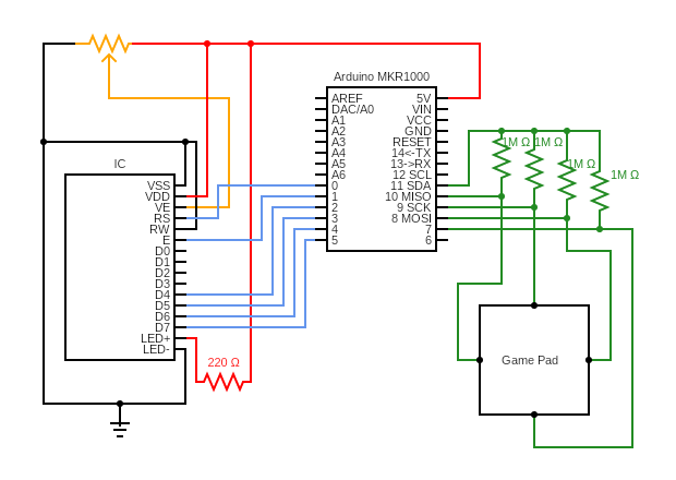
Wire up the following circuit. It is color-coded for clarity (the red lines go to +5V, the black lines go to ground, the orange line goes to the potentiometer, the blue lines go to the LCD, and the green lines go to the gamepad). The sub-steps of this step give you several hints and reference photographs for wiring, which we highly recommend you follow. We also suggest using both partners’ breadboards, because one breadboard does not fit both the LCD and the Arduino.
-
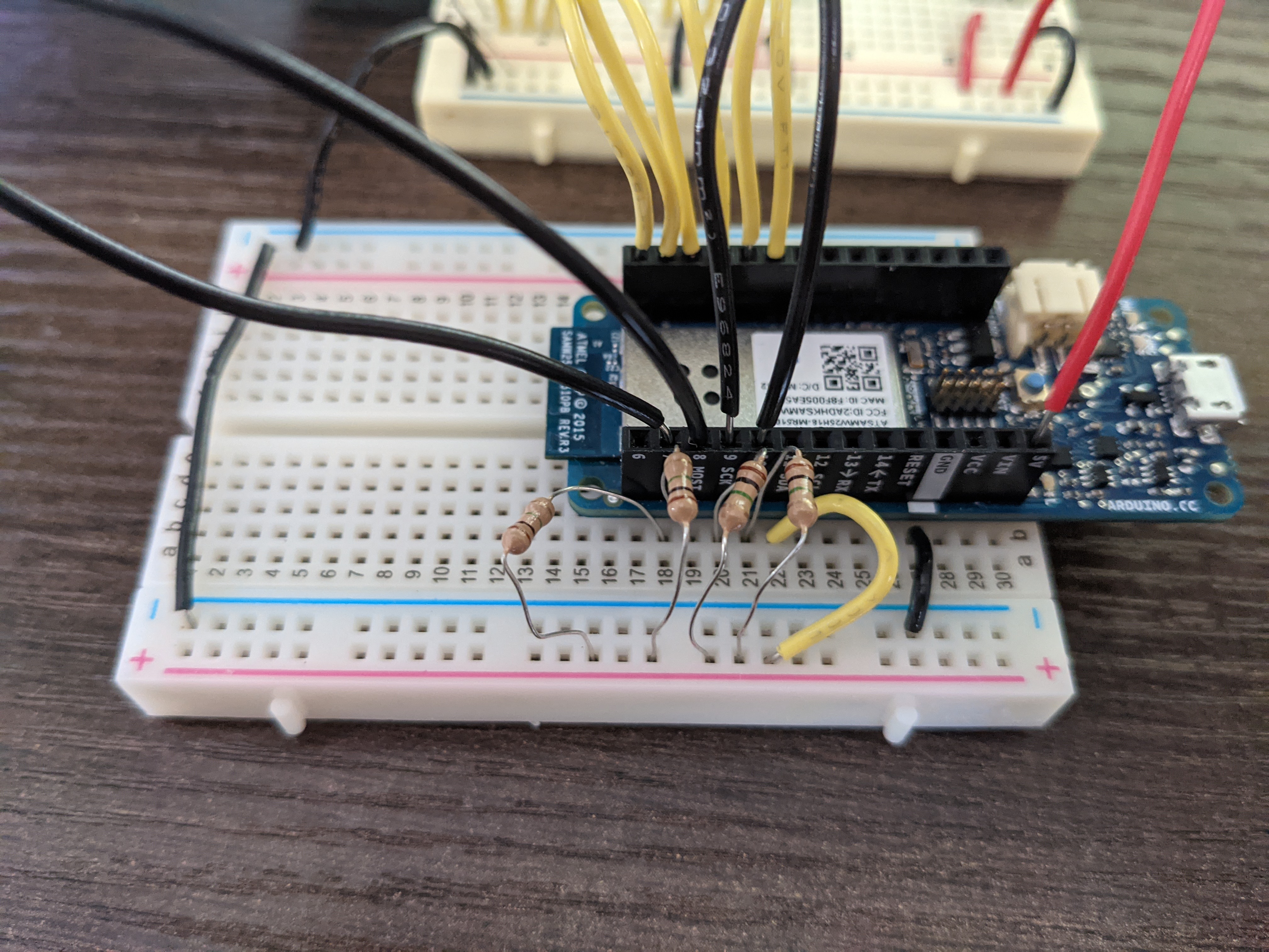
For wiring up the gamepad, it does not matter which wire of the gamepad goes into which of Arduino pins 7-10. You will configure this in code. We suggest using the red + rail of the breadboard to connect pin 11 to the resistors connected to pins 7-10, as shown. We also suggest putting the gamepad wires into the pin headers on the Arduino, rather than in the breadboard. Because the resistor legs are uncovered metal, take care to make sure that they are not touching each other, which may cause a short between two Arduino pins.
-
For wiring up the LCD, be sure to connect the upper ground rail of the LCD breadboard to the ground rail of the Arduino breadboard (which should be connected to the GND pin of the Arduino, just like in previous labs). We also suggest running a jumper from the Arduino 5V pin to the upper red “
+rail” of the LCD breadboard. Then, you can connect the potentiometer and relevant pins of the LCD to these rails. We also suggest putting the wires that run from the LCD to the Arduino into the pin headers on the Arduino, rather than in the breadboard, as shown.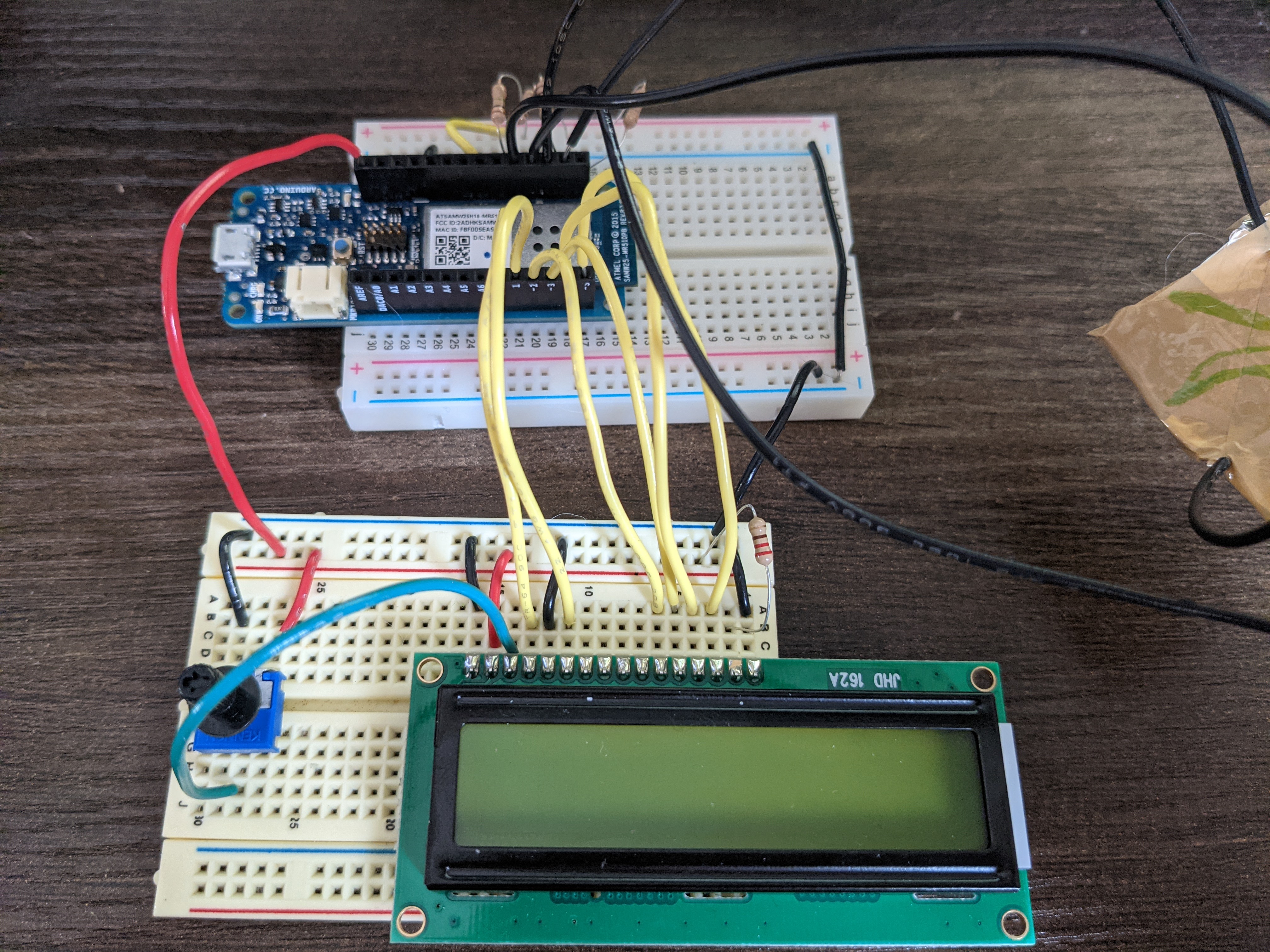
-
-
Download and extract the Lab 5 starter code and open the
lab5.inofile in your IDE. In theLibrary Manager(Tools -> Manage Libraries), install the “CapacitiveSensor” and “LiquidCrystal” libraries if they are not installed already. Upload and run the code on your Arduino, and open the Serial Monitor.-
You should see “CALIBRATING…” scroll across the LCD screen. If you do not see this, you may need to turn the potentiometer to adjust the contrast of the screen; or you have wired the LCD incorrectly and should double-check your circuit.
-
On the serial monitor, you should see “Capacitive sensing:” and then four values, preceded by 7, 8, 9, 10. Decide on an orientation of your gamepad (i.e. decide which side is “up”). Press your finger to the gamepad sensor that you decided corresponds to “up”, and observe which of the numbers goes up on the Serial Monitor. What threshold do you observe such that values under that threshold mean the gamepad sensor is not pressed, and values above the threshold means that the sensor is pressed? Change the corresponding values on lines 22 and 27 of the code (under the comment
LAB STEP 3b) such thatcap_sensors[UP]is one of 7, 8, 9, 10 corresponding to the value you observed changes, andthresholds[UP]corresponds to the threshold you decided. Repeat for the other three sensors. -
Comment out line 20 (the
calibrate()function call under theLAB STEP 3bcomment) and uncomment line 35 (thetest_calibration()function call under theLAB STEP 3ccomment). Upload and run your code. Observe the LCD screen: it should display nothing when no sensors on the gamepad are pressed, and display “X pressed” when sensor X is pressed, where X corresponds to UP, RIGHT, DOWN, or LEFT. If one or more sensors is miscalibrated, repeat Step 3b or check your circuit. -
Comment out or remove lines 20 and 35 (
calibrate()andtest_calibration()). Your code is now set up to take inputs from the gamepad.A note on the code: a lot of the underlying behavior (setting up the sensor and LCD, displaying custom characters on the LCD, reading sensors) is abstracted away into the
lab5_utils.inofile, along with the helper functions for this lab. While you do not need to read or modify this file for this lab, you may find it helpful refer to this file as well aslab5.hto see how certain types (likestate,orientation, andxyo) are defined and used. If your course project will use capacitive sensing or the LCD screen, you should take a look at how these components are set up so that you have a starting point for your own code.
-
-
Implement two helper functions (under the comments reading
LAB STEP 4) that correspond to the two tables from prelab step 2.You should use switch…case for these functions, instead of
if/else if/else. Remember to put abreakat the end of everycase!Write descriptive comments above both functions.
-
Under the comment reading
LAB STEP 5, initialize all of the variables according to your table in prelab step 3.x,y, andoare done for you as an example of how to use thexyotype. -
Compare your state chart design from prelab step 4 and your traceability table from prelab step 5 with your partner’s. Discuss and resolve any discrepancies before proceeding to the next step.
-
Under the comment reading
LAB STEP 7, implement the FSM from prelab step 4.This function takes the current state and the three inputs described in the prelab, modifies any of the state variables, displays something on the LCD, and returns the next state.
You should follow the conventions described in class, namely that the FSM is implemented as a
switch...caseon the state input, where eachcaseblock checks the transitions and performs actions if the transition needs to be taken. Some of the transitions from the prelab have been done for you, as a reference. Remember to return the current state for cases of stutter behavior, i.e. when a transition is not taken.-
Following the examples in the code, comment each transition guard checking with the annotation of the transition, e.g.
a-bfor a transition going from state a to state b (the state numbers of a and b suffice, rather than the full state name). -
With your partner, go through this code and check that each transition defined in the table of prelab step 4 has an annotation in the code. Also make sure that each transition produces an output by calling one of the three functions that displays something on the LCD.
-
Upload and run your code, and try playing the game. Even if the code does not work exactly correctly, get it checked off by a TA.
-
Spend up to the end of lab time debugging your code and state chart. We will revisit the code in the next lab (testing lab), so keep your circuit and make sure both partners have a copy of the code. You do not have to turn your code in for this lab.
-
Writeup
In a document, answer the following questions. Make sure the report states your name (first and last) and your partner’s name (first and last)! (if you worked alone, write “no partner”)
1. Think through the following list of concepts you encountered in the lab, and note if you have questions about any of them. Please also include any questions about concepts not listed here. If you have no questions, just write “no questions”
finite state machines (FSM), guards, actions, switch…case statements, requirements, traceability matrices, LCD screens, capacitive touch
2. What, if any, frustrations did you encounter while doing the lab?
3. What was your main takeaway from this lab?
4. Are you confident that your game code works according to the requirements in the prelab? If so, you can just answer “yes” to this question. If not, briefly (2-4 sentences), describe what you think the problem might be and/or how you plan to go about diagnosing the problem.
5. Including the pre-lab and writing this document, how long did this lab take you? You will not be judged on your answer for this question, the numbers are just being used for calibration purposes for later labs and future course offerings.
Turn in the document (saved as a PDF; separate from the zip of the code) on Canvas.