Embedded Programming and Memory
Table of contents
About
In this lab, you will interact directly with the registers for the AMD chip that operates your Arduino. While in previous labs you saw how to use the Arduino API to control input and output on pins, most MCUs do not come with such a useful layer of abstraction. In this lab, you will learn what happens under the hood of this abstraction, by setting bits in MCU control registers yourself. In doing this, you will gain some experience interpreting a datasheet for a device as complex as a microcontroller. In the last part of the lab, you will also get some sense of the memory limits of this microcontoller.
Revised on Sep 26, 2021 to add Step 1 of the lab procedure and to modify Step 7 of the lab/Step 4 of the writeup and add Step 5 of the writeup.
Lab 3 Rubric
Resources
- Arduino API
- Arduino Help
- MKR1000 schematic
- SAM D21E/SAM D21G/SAM D21J Datasheet Summary
- Atmel SAM D21 Family Datasheet DATA/STORAGE WARNING: 1115 page PDF
- SAM D21 peripheral header files
Materials
Included in your kits:
- Arduino MKR1000 and USB cable
- Breadboard
- 1 LED (any color)
- 2 push buttons
- 3 resistors (1 x 1kΩ; 2 x 10kΩ)
- Jumpers/wires
Provided:
- None necessary
Prelab (due date: September 28, 2021 at 4pm)
Duplicate the following worksheet and fill it out digitally; or print it, fill it out on paper, and scan it to turn it in. The idea is to be able to refer to this worksheet during the lab.
Lab Procedure
-
With your partner, come up with a high-level, 3-5 sentence summary of how Arduino code gets compiled to code that is compatible with the architecture of the microcontroller on the Arduino. Tell this summary to a TA. If you are waiting for a TA, go ahead and get started on the next steps of the lab.
-
Wire up the following circuit. At different steps in the lab, we will work with different parts of the circuit.
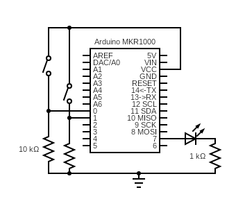
Test that each component is working by writing some code to turn on the external LED and the on-board LED (on pin 6) and output the signal of each button onto the serial monitor. You can just poll
digitalRead(...)for the buttons, instead of setting up an interrupt handler. If you need help debugging your lab, your TAs will first ask you to pull up this code to first make sure your circuit is working. -
Create a new sketch. In this sketch, you will work with the PORT registers to blink one of the LEDs.
-
Refer back to step 4 of the prelab, where you determined the register bits to set and clear to drive Pin 6 as an output.
-
To read and write to the port registers in Arduino code, you can access them using
PORT->Group[PORTX].REGNAME.reg, whereXisAorB(the port you are referencing), andREGNAMEis the name of the register, likeDIR. -
Write some Arduino code to use the registers to change the mode of Pin 6 to output, and drive it high (on) for 1 second and drive it low (off) for two seconds. You may use
delay(...)in your code, but notpinMode(...)ordigitalWrite(...). It may be helpful to look back at the review of bit operations in step 2 of the prelab. -
Upload, run, and debug your code, and, when working, get it checked off by a TA.
-
-
Now, you will modify the code to read the input from one of the buttons and use it to drive the LED on when the button is pressed down and off when the button is not pressed.
-
Referencing the same documentation as above to see what register bits to set or clear, set the mode of Pin 0 to input, and read its input value. Write some code to control the built-in LED with the button. When the button is held down, the LED should be lit. When the button is released, the LED should not be lit. Again, you may not use
pinMode(...),digitalWrite(...),digitalRead(...), orattachInterrupt(...)in your code. -
Upload, run, and debug your code, and, when working, get it checked off by a TA.
-
Save the code as
registers1.inoto be submitted later.
-
-
Create a new sketch. In this sketch, you will set up an interrupt on Pin 0 to detect the rising edge of the signal, indicating that the button has been pressed.
-
Configure Pin 0 as an input as above. Also configure the pin to be used by the External Interrupt Controller (EIC) based on your answers in prelab step 6.
The SAM D21
port.hheader file file gives some convenient definitions of the bits. For example, instead of manually writing bit 2 to PINCFG to enable the pull resistor, you can use the pre-defined macroPORT_PINCFG_PULLENwithout needing to shift the bits, so you can connect all the relevant flags with a bitwise-or:PORT->Group[PORTX].PINCFG[y].reg = PORT_PINCFG_PULLEN | ...As alluded to in prelab step 6, you will reference the relevant PMUX register using
PORT->Group[PORTX].PMUX[y/2].reg -
Use
Serial.println(...)to print the PM and NMI registers from steps 7 and 8 of the prelab to the serial monitor in binary, so that you can verify that the necessary bits are already set. PM registers can be accessed usingPM->REGNAME.reg, and similarly with NMI. -
Configure the GCLK according to the bits you determined in step 9 of the prelab. Macros that name these bits (for example,
GCLK_GENCTRL_IDCare found ingclk.hin the header files.15.6.6 tells us that when we write to GENCTRL, we need to also wait for the SYNNCBUSY bit of the STATUS register to clear before proceeding, which we can do by adding the following line after writing to GENCTRL:
while(GCLK->STATUS.bit.SYNCBUSY);
-
Now that we have configured the generic clock, it is time to configure the EIC, using your table from prelab step 10. You can refer to
eic.hin the header files for the bit macros. You can reference the registers usingEIC->REGNAME.reg. -
Finally, enable the EIC using the CTRL (21.8.1) register. Because CTRL is write-synchronized, we also need to wait for the
EIC->STATUS.bit.SYNCBUSYbit to clear, as for the GCLK STATUS SYNCBUSY bit above. -
Enable interrupts on individual pins by writing a 1 to the appropriate index bit of the INTENSET register (21.6.6/21.8.7).
-
The nested vector interrupt controller (NVIC) manages all the interrupts on the board. We set the priority of the EIC at 3 because the button push isn’t timing-critical, and we also enable the interrupt request definition (IRQ, the function that handles the interrupt) using the following two lines:
NVIC_SetPriority(EIC_IRQn, 3); NVIC_EnableIRQ(EIC_IRQn); -
Finally, we implement the function
void EIC_Handler(void)with the behavior we want. For this code, you should increment the number of times the button has been pushed, and print the number to the serial monitor every time the button is pushed. You must write a 1 to the appropriate index bit of the EIC INTFLAG register to clear the interupt at the end of the handler function (21.8.8).
-
Upload, run, and debug your code. If it is not working, carefully read through every substep of this lab step, to see if you missed configuring any registers. Once you are confident your code works demo it to a TA.
-
-
In this step, you will enable interrupts on the other button (pin 1). Remember to check which Port/pin Arduino pin 1 is on, and which EIC index corresponds to that port pin. You will then change the EIC_Handler function such that the external LED toggles between on and off whenever the pin 1 button is pressed, and the on-board LED toggles between on and off whenever the pin 0 button is pressed:
-
You should configure both LEDs as outputs, just like you did for the on-board LED in Step 3.
-
You should configure pin 1 the same was you did pin 0, by writing the corresponding registers. Note that the EIC handles all external interrupts on all pins, so your GCLK configuration shouldn’t change. You will, however, need to enable some extra bits on the three EIC configuration registers.
-
When an interrupt is triggered and the EIC_Handler function, you can check which EIC index is responsible for the interrupt by reading the INTFLAG register and seeing which bit is a 1. After handling the interrupt, you then write a 1 to that bit again to clear the interrupt. This may be unintuitive, but that is why this register is called the Interrupt Flag Status and Clear register (see 21.6.3).
How would you check if a bit at a certain index of a register is set? Refer back to pre-lab step 2 and discuss with your partner.
Implement this check to determine which button was pushed, and toggle the external LED when the pin 1 button is pressed and the on-board LED when the pin 0 button is pressed.
-
Finish writing your code, and upload, run, and debug it. When it is working, check it off with your TA.
-
Save the code as
registers2.inoto be submitted later.
-
-
You can do this last step during lab with your partner, or alone. This step requires your Arduino but doesn’t require you to build any circuits.
-
Create a new sketch that declares and initializes two global variables (of types(s) of your choosing), two local variables in the
setup()function, and an emptyhelper()function. Keeploop()empty as well. -
Using
Serial.println(...)in thesetup()function, print out the memory addresses of both global variables, both local variables, theloop()function, and thesetup()function in hexadecimal. You can access the address of a variable or function by preceding it with&:&varnameor&loop(don’t put the parentheses after the function name, because you are not calling the function). You can print something in hex usingSerial.println((unsigned long) thing_to_print, HEX). -
Now declare a global variable of type
int*namedaddr. In thehelper()function, declare and initialize a local variable of typeint. Write down the value you initialized this variable to. Inhelper(), store the address of this variable intoaddr(to get the address of a variable, precede it with&, i.e.addr = &var). Back in thesetup()function, callhelper()and then dereferenceaddrto print the value stored at that address:Serial.println(*addr). Write down this value. -
Now change the type of the local variable in
helper()tostatic intand run the code again. Write down the value stored ataddrafter runningsetup. -
Save these values to be included in the writeup.
-
Writeup
In a document, answer the following questions. Make sure the report states your name (first and last) and your partner’s name (first and last)! (if you worked alone, write “no partner”)
-
Think through the following list of concepts you encountered in the lab, and note if you have questions about any of them. Please also include any questions about concepts not listed here. If you have no questions, just write “no questions”
ports, registers, datasheets, interrupts, interrupt flags, bit manipulation, memory -
What, if any, frustrations did you encounter while doing the lab?
-
What was your main takeaway from this lab?
-
Include the locations for the two global variables, two local variables and the two functions from Step 7b. Based on the memory diagram in the SAM D21E/SAM D21G/SAM D21J Datasheet Summary (section 6) and what you learned in the reading/lecture, what does that tell you about how and where space for the variables is allocated? In particular, for variables being declared in a specific order in code, is there a specific direction in which the memory being used “grows”?
Are the memory address formats consistent across variable types and functions? Based on what you learned about memory architectures, why is/is not this the case? (hint: if a number starts with zeroes, Serial.println() does not print those zeroes, so you need to remember that they are implicitly there.)
-
Explain the differences in values (if any) that you observed in steps 7c and 7d, using your understanding of the
statickeyword. -
Including the pre-lab and writing this document, how long did this lab take you? You will not be judged on your answer for this question, the numbers are just being used for calibration purposes for later labs and future course offerings.
Turn in the code (registers1.ino and registers2.ino zipped into one folder) and the document (saved as a PDF; separate from the zip of the code) on Canvas.