Sensors, Actuators, and I/O
About
In this lab, you will continue to get experience wiring circuits and writing Arduino code. This lab introduces the analogWrite and analogRead functions and has you explore how to use them with multiple different input and output devices in your kit. By the end of this lab, you should have a deeper understanding of how to manipulate and read voltages in embedded circuits, by use of pulse-width modulation (PWM), Analog to Digital Converters (ADCs), Digital to Analog Converters (DACs), and voltage divider circuits.
Lab 2 Rubric
Resources
Materials
Included in your kits:
- Arduino MKR 1000 and USB cable
- Breadboard
- 2 LEDs (recommended red)
- 3 resistors (3: 1kΩ)
- 1 capacitor (100 μF)
- 1 RBG LED
- 1 potentiometer
- Jumpers/wires
Provided:
- None necessary
Steps
Note: during the course of this lab, you will make one graph that you will be asked to discuss in your lab document. We suggest making and saving this graph in a Google sheet, shared with you and your partner (if you have one), so that you can reference it later.
For these and the following labs, we do not show ground explicitly connected to the GND pin of the Arduino, to make the diagrams less cluttered. You should ALWAYS connected the GND pin of the Arduino to the ground rails of the breadboard, as described in Lab 1.
-
Build a circuit to explore a visual representation of PWM:
-
Recall from class that PWM is a way to simulate analog (continuous) output using a digital signal. The duty cycle of a PWM signal can vary from 0% (always off) to 100% (always on):
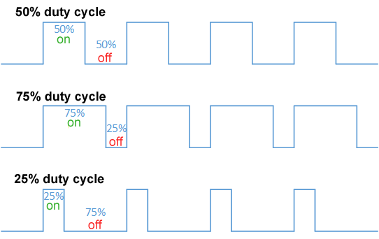
(image from Wikipedia)
Discuss with your partner (or think to yourself) about what you expect to happen to an LED driven by a 50% duty cycle signal.
-
On your breadboard, build the following circuit. We recommend using a red LED for brightness/visibility:
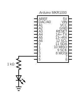
-
Read about analogWrite(…). In particular, pay attention to the format of the duty cycle input, which is a whole number rather than a percentage. With that understanding, read the following code and make sure you understand what it does:
/* * Opens serial communication between the MKR1000 and the computer * Takes in a number 0-255 from the serial monitor and sets the output PWM duty cycle on LED_PIN to that number */ int LED_PIN = 4; void setup() { Serial.begin(9600); while (!Serial); // Wait for Serial to initialize Serial.println("Ready!"); analogWrite(LED_PIN, 0); } void loop() { if (Serial.available() > 0) { int input_pwm = Serial.parseInt(); Serial.parseInt(); // Ignore null character if (input_pwm < 0 or input_pwm > 255) { Serial.println("Input out of range; ignoring"); } else { Serial.print("Received input of "); Serial.println(input_pwm); analogWrite(LED_PIN, input_pwm); } } } -
Copy the code into a new Arduino sketch. Open the Serial Monitor (
Tools > Serial Monitor) and upload it to the Arduino. -
Play around sending different values through the serial monitor. What happens to the LED? Does it match your intuition? Can you give a concrete explanation, based on the Arduino PWM frequency listed in the documentation you wrote, and on the frequency at which the human eye perceives?
-
-
To see numerical evidence to back up your intuition, and to explore
analogRead(...), we will use a capacitor to smooth a PWM signal.-
Think about how you would measure the average voltage output by a PWM pin. One way is to use
digitalRead(...)and average a sample of the results. This might lead to different or even incorrect results based on the sampling frequency, which depends on multiple factors, including how long thedigitalRead(...)takes and how long any computation takes between samples. Imagine if the sampling frequency were the same as the PWM frequency. Then, we would sample the same point of the PWM curve every time, and always measure the same voltage, which would not give us the correct average: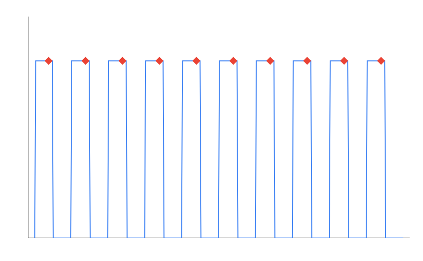
Instead, we will use a circuit component to do some averaging for us.
-
Construct the following circuit:
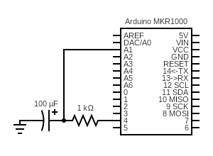
To understand what components go in this circuit, it might be helpful to glance at the images on the Wikipedia page for Capacitor. Pay attention to the polarity of the capacitor! The anode (positive side) has a little + printed next to the leg, and typically has a longer leg.
-
A capacitor stores electric energy. When it receives a voltage, it gradually charges up, and when the voltage source is gone, it gradually discharges. For a PWM circuit, that charging and discharging lead to a voltage across the capacitor that resembles the red line here:
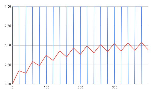
Hence, given enough PWM cycles, the voltage across the capacitor will settle to a small error around the average voltage of the PWM signal.
-
Write some Arduino code to measure the voltage across the capacitor, by calling analogRead(…) on pin
A1. Your code should set the output of pin 4 to a variable representing a PWM duty cycle from 0-255, wait a fraction of a second, and read the voltage on pinA1.Note that the
analogRead(...)outputs a number from 0 to 1023 (resolution of 10 bits for the MKR1000), so your code will have to do some math to convert this value to a voltage between 0 and 3.3V.Your code should change the PWM duty cycle on pin 4 from 0 to 255 by increments of 5, and use
Serial.print(...)andSerial.println(...)to print comma-separated values of duty cycle and capacitor voltage (see the code in step 1c for an example of how to set up serial and how to print multiple strings to the same line). For example, the first line will likely read0, 0.0. -
Run this program on the Arduino and copy the serial output to a spreadsheet. On Google sheets, you can paste comma-separated lists into a single column and then click the clipboard at the bottom-right of the pasted selection and select “Split text to columns.” Graph the curve of PWM duty cycle vs. voltage across the capacitor. Is this the result you expect? Why or why not?
Get your graph checked off by a TA.
-
-
While in some ways PWM approximates a continuous (analog) output signal, it is important to understand the difference between the two. Construct some circuits to see the difference between the two in practice:
-
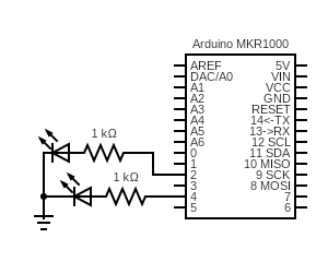
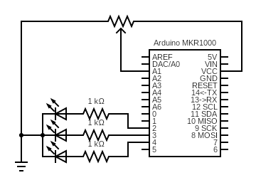
First, construct the circuit below. We suggest red LEDs for brightness/visibility:
-
Using analogWriteResolution(…), set the analog write resolution of the Arduino to 8 bits. This will make things consistent with the DAC pin we will use in the next step. Write some Arduino code to drive each of the LEDs with a PWM with 50% duty cycle (input of 127 to
analogWrite(...)) -
Upload your code to the Arduino. You should observe both LEDs glowing at the same, half-dim brightness. If this doesn’t happen, your LEDs might be deficient, or you are calling
pinMode(...)before callinganalogWrite(...), which you shouldn’t do. -
Unplug the Arduino and change the pin driving one of the LEDs to the DAC/A0 pin:
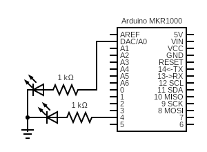
This pin has a Digital to Analog Converter, which means that
analogWrite(...)outputs a desired voltage between 0V and 3.3V, instead of a PWM signal. -
Update your code from step 3b to drive the LED with the
A0pin, at half-voltage (input of 127 toanalogWrite(...)). Except for changing the pin number, nothing else about your code should change. -
Upload your code to the Arduino. What do you observe? Why do you think this happened? Discuss it with your partner or ask a TA for a hint. You will be asked to answer this question in your own words for the lab writeup.
-
-
One of the powerful things about microcontrollers is that you can write code that makes the output of some components respond to the input of other components. This provides more flexibility and functionality than hooking up the components directly in a circuit. To see this in practice, you will use a potentiometer to controll an RBG LED.
-
You will be using a potentiometer for this step. To understand how a potentiometer works, first consider this voltage divider circuit with a fixed supply voltage
Vand fixed resistancesR1andR2: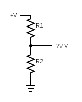
When resistors are in series (connected one after the other), the total resistance across them is the sum of their resistances, or
R1 + R2. The current will be the same through the whole circuit, and by Ohm’s law will be equal toI = V/R = V/(R1 + R2).Because the current through the bottom resistor is equal to this computed
I, we can compute the voltage across the resistor using Ohm’s law again:??V = IR = (V/(R1 + R2)) * R2 = V * R2 / (R1 + R2).Hence, by choosing values of
R1andR2, you can divide the supply voltage to whatever lower value you want. BecauseR1andR2are fixed for any specific circuit, this divided voltage will also be fixed.A potentiometer works on the same principle. While different potentiometers work in different ways, conceptually, you can imagine it internally changing the values of
R1andR2as its dial is turned. This means that, a potentiometer can be set to output any voltages in between 0 and its supply voltage while the circuit is on. -
Armed with this knowledge, you can work with the following circuit. Construct it on your breadboard:
The potentiometer symbol, fittingly, looks like a resistor with an arrow pointing to it, to symbolize the variable internal resistance ratios. Your potentiometer looks like a blue square with two legs on one side and one leg on the other. The control knobs for your potentiometers are in a separate bag in the kit, and look like small black plastic rods. Firmly insert one of them into the body of the potentiometer to assemble it. The potentiometers are not polarized, meaning you can connect the side with two legs to ground and VCC in either configuration. Be sure to use VCC, not 5V!! The leg on the side by itself should get connected to the analog pin.
Instead of using three separate LEDs in this circuit, use your RBG LED. It looks like a white LED with four legs. Yours are common cathode, which means that the cathode (longest leg) should be connected to ground. The other four legs control the red, blue, and green outputs of the LED and should each be connected to a different resistor and Arduino pin.
-
Write some code that changes your LED from blue, to purple, to red, to yellow, to green, to teal, back to blue as you turn the potentiometer (where you start and end this cycle doesn’t matter, as long as the whole progression is there in order). Use
analogRead(...)to read in the values of the potentiometer, and useanalogWrite(...)to send a PWM signal to each channel on the LED.One channel of the LED should be off at all times, and the duty cycles of the other two should sum to 255 to maintain a constant brightness. For example, when changing from blue to red, the green LED will be off, and the duty cycles of blue and red will change from B=255, R=0 for completely blue, to B=127, R=128 for purple, to B=0, R=255 for completely red, with intermediate values computed to make a smooth transition. Talk through how you will write this code with your partner, and ask your TA for a hint if needed. Hint: our solution made use of the map function to cut down on the amount of math we had to do.
-
Upload and run your code on the Arduino. Debug your circuit and code, and, when you’re confident that it works, get it checked off by a TA. You now know how to use
analogRead(...)andanalogWrite(...)to interact with input and output components using code! Hint: if one or more colors of the RBG LED don’t seem to be working, verify that your LED is functional by writing code that turns each one on individually (writing a PWM duty cycle of 255 to one pin and 0 to the other two).
-
-
Turn in your work and complete the report:
-
Save your code from steps 2d and 4c and name them 2d.ino and 4c.ino. Zip all of the files up and make sure each partner has a copy.
-
In a document, answer the following questions. Make sure the report states your name (first and last) and your partner’s name (first and last)! (if you worked alone, write “no partner”)
1. Think through the following list of concepts you encountered in the lab, and note if you have questions about any of them. Please also include any questions about concepts not listed here. If you have no questions, just write “no questions”
PWM, ADC, DAC, voltage dividers, memory, capacitors, potentiometers, rbg LEDs2. What, if any, frustrations did you encounter while doing the lab?
3. What was your main takeaway from this lab?
4. Include your graph from Step 2e. In your words, explain the similarities and differences between a PWM signal and an analog signal, based on what you observed in Step 3f.
5. Read about the attachInterrupt(…) function. What code would you write to turn the “decrease” button push in the Lab 1 binary counter from an input we polled into an input that triggers an interrupt? Assume you handle the interrupt in a callback function called
decreaseButton(). The one-line function call toattachInterrupt(...)suffices as an answer here.6. Including writing this document, how long did this lab take you?
-
Turn in the code and the document (saved as a PDF) on Canvas.
-