Introduction to Arduino
Due 9/23/21 at 7pm
About
This lab introduces you to the Arduino platform and to working with basic circuits. By the end of this lab, you will have been introduced to the Arduino IDE and some basic Arduino programming. You will also have used a circuit diagram to wire up some circuits with LEDs, resistors, and push buttons.
Lab 1 Rubric
Resources
Materials
Included in your kits:
- Arduino MKR 1000 and USB cable
- Breadboard
- 3 LEDs (any colors)
- 5 resistors (to be determined by you during the lab)
- 2 push buttons
- Jumpers/wires
Provided:
- None necessary
Steps
-
Install the Arduino IDE:
- On your personal computer, install the Arduino IDE from the link
Or
- On a lab machine, navigate to the Microsoft app store and search for Arduino. Install the software.
- On either machine, when the IDE is installed, open it. Under the
Toolsmenu, make sureBoardreads Arduino MKR1000. If not, use the menu to select it. You might have to use the Boards Manager link in the menu to install the Arduino SAMD Boards drivers (find them by searching for MKR1000 in the Boards Manager, and double-click to install).
-
Load your first program onto the Arduino:
-
Under the
File > Examplesmenu in your IDE, open01. Basics > Blink. This opens an example Sketch (Arduino program) calledBlink. Take a moment to read through the code, including the documentation at the top, with your partner. -
Connect your Arduino to a USB drive on your computer using the orange USB cable. You can keep the Arduino pins in the foam it came with for this step.
-
Use the upload button to upload the Sketch to the board.
 Image credit: Arduino 101
Troubleshooting: if you get an error about a device not found on a port, try selecting a different port in the
Tools > Portmenu. -
Observe the on-board LED (near the 5V pin) blinking, with the LED toggling between ON and OFF every 1 second.
-
-
Edit the sketch to make the LED blink twice as slowly. Upload the code and verify that the LED is blinking slower.
-
Edit the sketch to make the LED gradually change from blinking slowly, to blinking quickly, and back:
-
Reference the Arduino Language Reference on Structure for the syntax of
forloops,ifstatements, etc. -
The delay between toggling the LED on and off should change from 2000 ms to 100 ms and back to 2000 ms in increments of 100ms. Concretely, the LED should be on for 2000 ms, then off for 2000 ms, then on for 1900 ms, then off for 1900ms, then on for 1800 ms, then off for 1800 ms, and so on, counting down to 100 ms, and then counting back up to 2000 ms.
-
Observe that the
loop()function of the sketch will repeat forever. Instead of making afor loopinside this function, use global variable(s) that you initialize in thesetup()function and manipulate in theloop()function, such that you only calldigitalWrite(...)twice during each iteration of theloop()function. -
Upload, observe, and debug your code. When you are confident that it works, get checked off by a TA.
-
-
Run the same code using an external LED, by connecting your first circuit on the breadboard:
-
You will connect a physical LED to the MKR1000. Study the pin labels on your Arduino. Some have special roles, such as
GND(ground pin),VIN(input voltage, if you were, for example, supplying battery power), andTXandTR(for serial communication). There are also 7 analog pins (A0-A6) and 8 pins just for digital I/O (simply labeled0-7). Because an LED requires a digital (on/off) signal, we will be using one of the digital I/O pins, namely 4. -
Study the following circuit diagram. The Arduino is represented as a rectangle with labels for all of its pins. Electrical connections are represented by black lines, with solid dots representing junctions (meaning that the wires/components are physically connected). The LED
 is connected to pin 4, then to a resistor
  , and then to ground
  . Here, we explicitly show that the circuit is grounded using the
 GNDpin of the Arduino, by connecting the ground symbol to that pin on the diagram.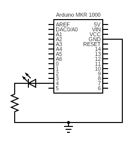
-
The LED is connected to a resistor because the LED itself has negligible resistance. Recall that Ohm’s law says that
V = IR. The Arduino pins supply a constant non-zero voltage. If there were no resistor, thenR = 0and the circuit would keep drawing current until the Arduino got damaged.The maximum current each Arduino pin can safely supply is 7mA. To be safe and also make the math easy, we will limit the pin to supplying about half of that, or 3.3mA. Given that the voltage output of the pin is 3.3V, and that
V = IR, what is the minimum value ofRto limitIto 3.3 mA? Once you have your answer, select the corresponding resistor from your kit, by deciphering the resistor color codes.Get your resistor choice checked by the TA before you proceed to wiring up your circuit.
-
Before wiring up your circuit, it is good practice to connect the ground rails to ground. If you haven’t used a breadboard before, take a moment to review the way the pins are connected. All of the sockets in each of the 4 power distribution rails (the red
+and blue-lines) are connected along the rail. In the main part of the breadboard, each column of 5 sockets is connected. So, to connect both ground rails to the ground of the Arduino, you should connect theGNDpin to one of the rails, and connect the rails to each other.
When plugging the Arduino into the breadboard, make sure the two rows of Arduino pins are separated by the middle channel of the breadboard. Also make sure that the Arduino is seated firmly in the breadboard (you might have to apply some pressure to the Arduino. To avoid damage, it is good practice to press down on the black plastic pin headers rather than the metal).
Now, you can ground any circuit by connecting it to any hole on either the top or bottom ground rail!
-
Disconnect your arduino from power (unplug the cable) and wire up the circuit. Note that an LED has an Anode and Cathode, meaning that the circuit won’t work if you plug the LED in backwards. Helpfully, the legs of most LEDs, including the ones in your kit, are unequal lengths, to help you orient them. The anode is the longer leg.
Before powering up the circuit, go through the circuit checklist.
Get your circuit checked off by a TA before proceeding to the next step
-
In your code, create a constant global variable for your LED pin, with value 4. Change all appearances of
LED_BUILTINin your code to this variable. -
Connect your Arduino to the computer and upload your code, verifying that the LED you added lights up instead of the on-board LED.
Get checked off by a TA
-
-
Practice wiring up a button:
We will implement the switch
 using a push button. A push button enables a connection between the voltage source (VCC) and the input pin when pressed. To do this, a push button is connected like this (the orange wire is going to pin 5 of the MKR1000, the red wire is connected to VCC, and the black wire is connected to GND):
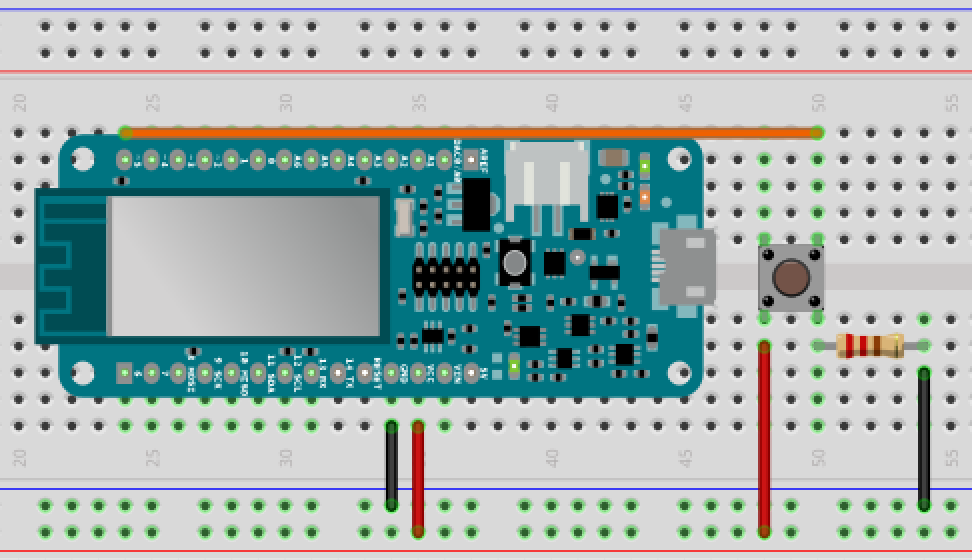
Image credit: Brian Carbonette on Arduino Project Hub
-
Wire up your circuit. Make sure the button is connected to VCC, not 5V!!! Do not use the same resistor as in the breadboard graphic above, but instead use the resistor color codes as a reference to find the 10kΩ resistor.
-
Study and run the following skeleton code:
/* * Prints the result of the button press to the serial monitor. */ int BUTTON_PIN = 5; void setup() { Serial.begin(9600); while (!Serial); // Wait for Serial to initialize pinMode(BUTTON_PIN, INPUT); } void loop() { Serial.println(digitalRead(BUTTON_PIN)); } -
Open the Serial Monitor (
Tools > Serial Monitor) and observe the output change as you press and release the button.
-
-
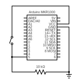
Now, implement a binary counter using this circuit:
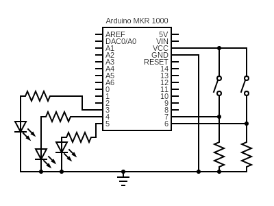
The resistors connected to each of the LEDs have a resistance of 1 kΩ. The resistors connected to each of the buttons have a resistance of 10 kΩ.
Remember that crossing lines are only physically connected when there is a solid dot at the junction of the lines. Otherwise, interpret the wires as crossing over each other without being connected.
-
Each of the 3 LEDs represents a binary digit. The most significant digit is connected to pin 3. As an example, for the LEDs connected to pins 3-5, refer to the LEDs as
L2,L1, andL0, respectively. IfL1andL0are on butL2is off, this displays011and represents 3 in binary. Wire up your circuit and use the checklist to check it. -
The push button on pin 7 is to decrement the counter, and the push button on pin 6 is to increment the counter. If the decrement button is pushed, the LED binary counter should decrement by 1. If the decrement button is pushed when the counter is displaying a 0 (all LEDs off, representing binary
000), nothing should happen. Similarly, if the increment button is pushed, the LED binary counter should increment by 1, and if it is pushed when the counter is displaying 7 (all LEDs on, representing binary111), nothing should happen. Assume that only one button is pushed at a time. Also assume that the counter starts at 0. -
Start a new sketch (using
Examples > 01. Basics > Bare Minimumgives you skeleton code to start with) and implement the functionality described above. Remember to usepinMode(...)to define pins as inputs or outputs. The input from the buttons can be ready usingdigitalRead(...). -
Upload your sketch to the Arduino and verify if it works. If it does, congrats! Get checked off by the TA, and you are done with the in-class portion of the lab. Otherwise, spend at least 15 minutes debugging with your partner before asking a TA for help. We suggest using Serial.println(…) and
Tools > Serial Monitoras in Step 6 to print debug information.Hint: your first instinct may be to poll
digitalRead(...)for a high signal, making the numbers increment rapidly as long as the button is pushed, rather than checking for the edge where it changes from 0 to 1. How do you detect this change?
-
-
Turn in your work:
-
Save your binary counter sketch as
lab01_bincount. Make sure each partner has a copy oflab01_bincount.inoto upload onto canvas. -
In a document, answer the following questions. If working with a partner, these questions should be answered individually (such that each partner turns in the code and their own responses in the document, separately). Make sure the report states your name (first and last) and your partner’s name (first and last)! (if you worked alone, write “no partner”).
1. Think through the following list of concepts you encountered in the lab, and note if you have questions about any of them. Please also include any questions about concepts not listed here. If you have no questions, just write “no questions”
Arduino IDE, Ohm’s law, circuit diagrams, LEDs, push buttons, Arduino API, debugging, other terminology
2. What, if any, frustrations did you encounter while doing the lab?
3. What was your main takeaway from this lab? 1-3 sentences are sufficient for this response.
4. In this lab, you worked with digital input (button) and output (LED) components. In the next lab, you will work with analog components. Describe how analog and digital components differ (if you use an online source while answering this question, cite it). Looking through the list of components in your Arduino kit, which input/output components are digital and which are analog?
5. Including writing this document, how long did this lab take you?
-
Turn in the code and the document (saved as a PDF) on Canvas.
-